I love precision machinery of all kinds. And I love well made cameras. I will sit for hours holding, handling, playing with one of my cameras and derive real pleasure from that. (My wife thinks I’m nuts ….) That is why I talk so much about how a camera “feels” as well as how it functions functions.
A natural corollary to this love is a desire to look inside my cameras and see how they function. I thought maybe you might also be curious. So lets go inside a TX. This one is not working but cosmetically it is very pleasing. Maybe we can fix it!

As I write this I have only gotten as far as taking the top of the camera. There is a long way to go to see how it works. I will add to this posting as I work my way through this machine. It may take some time so be patient and check back occasionally.
I don’t recommend you do this at home. However, if you want to, chose an old non-functioning camera, one that is not worth very much. Check E-bay for the value of your intended victim. I don’t want to see any Hansa rangefinder Canons being torn apart!
I chose the TX because I had a non-functioning one that I acquired for $10.00. I was also interested because it is purely mechanical, I think, except for the light meter circuits which should be pretty simple to digest.
A few cautions. First, we want to fix whatever the problem in this camera is and we want to put it back together. So, keep notes of what you do and in what order. Or, as I have done here, take copious photos so you can retrace your steps.
Secondly, clear a work space and light it well. Lay down a large sheet of white paper that yu can write on as you go but work over a piece of cloth or paper towel. Small screws and pieces can bounce and they are so small you will never find them. If they have a soft surface to land on, no bounce.
If you want to try this, you will need some basic tools. Get on E-bay and search for “camera repair tools” and do a Google search as well. There is all kinds of advice on what you will need.
I am sure that I will think of more cautions to give you as we go along. But, for now, let’s get started.
Removing the Top Cover
Well, nothing can happen till we open the package – which means taking off the top cover. And to do that we will have to remove the dials and levers on the top plate.
1.
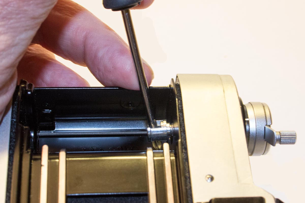
Let’s start by removing the rewind crank. We put a screw driver into the notch at the end of the shaft and then screw off the top part of the crank with the handle. Watch when you take the shaft out: there is a small ball bearing that drops out. You don’t want to lose it!
2.
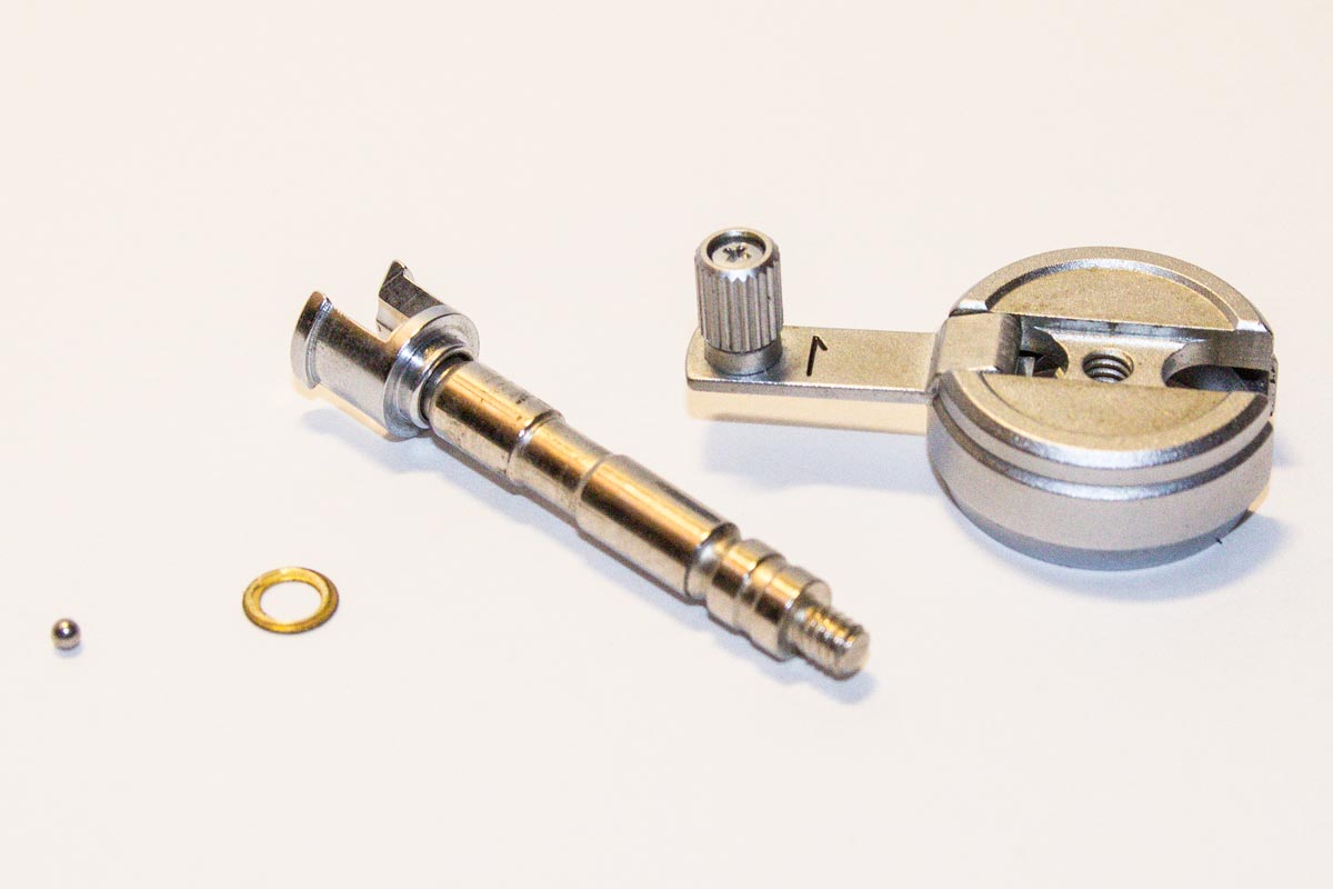
Here are the parts you will end up with. Note the small ball bearing on the left. The crank simply screws off the shaft. I put the parts from each stage in their own little plastic bag to keep them straight for reassembly (he said optimistically …!).
3.

Now we go to the right side of the top plate and take off the winding crank. On this camera you use an adjustable spanner made for this kind of connection. Be very careful that the points don’t jump out of the holes and scratch the surface!
4.
Under the winder lever there are two screws set at an angle that have to come out to remove the next assembly.
5.

Once they are out the large washer comes off and the lever is free to lift off.
6.
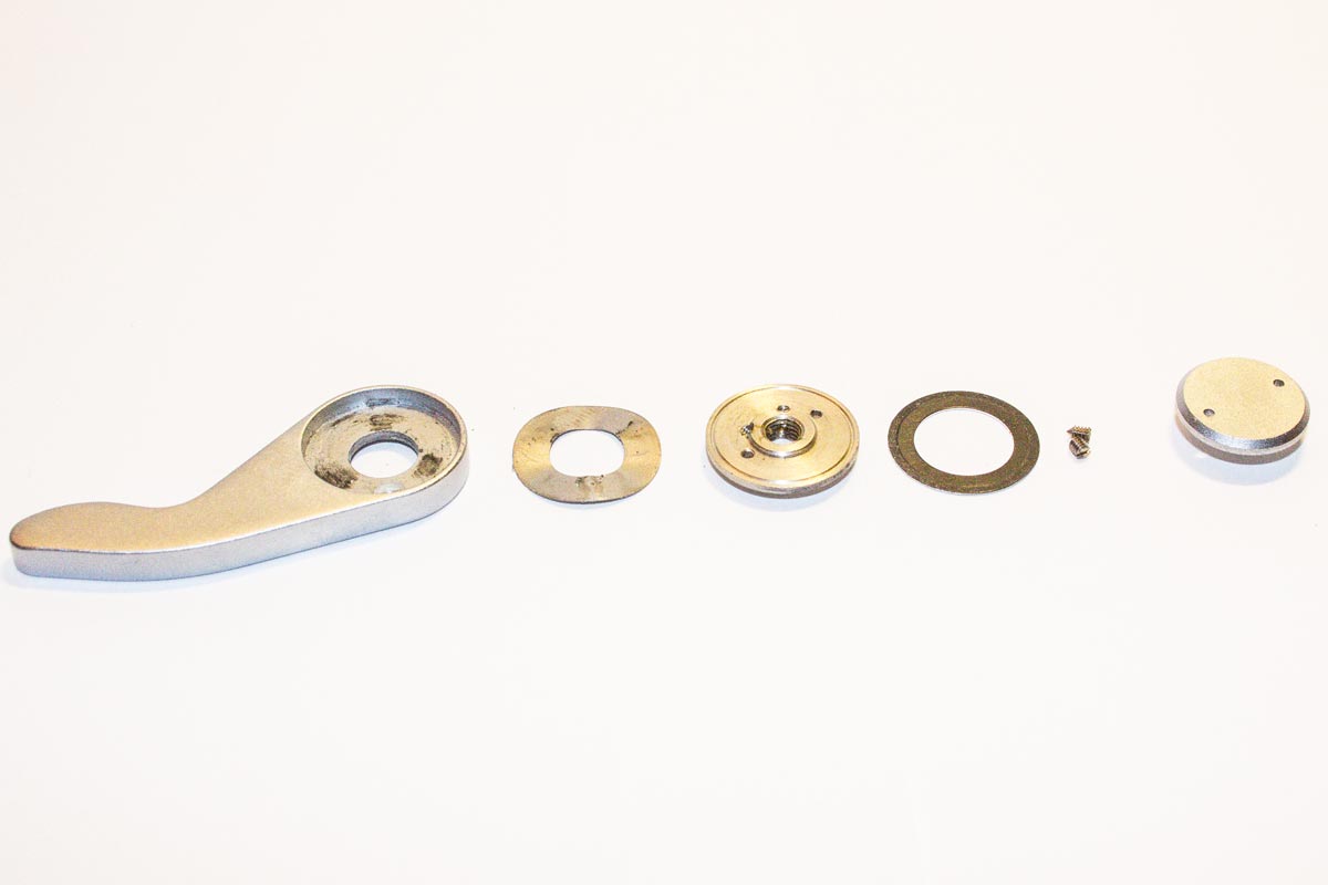
And here are the pieces from removing the advance lever laid out in the order they came off starting on the right end and proceeding to the left.
7.
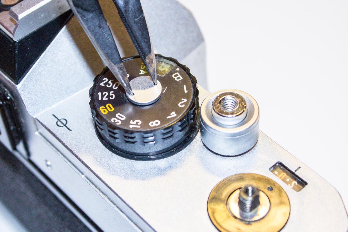
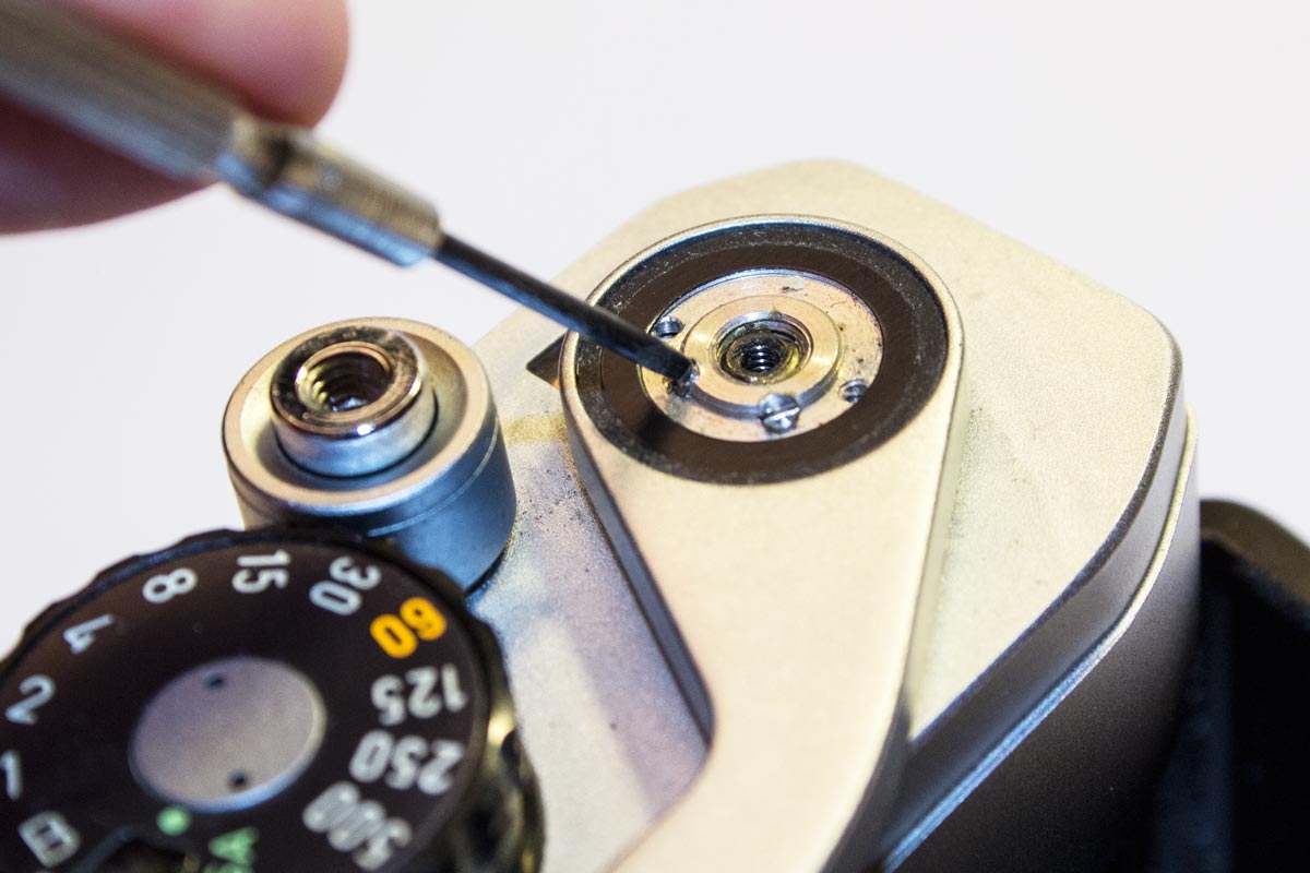
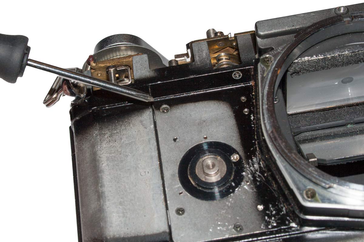
Next we have to remove the speed dial by taking out the center post. This is done with a specialized spanner (which I made myself from an old caliper set).
8.

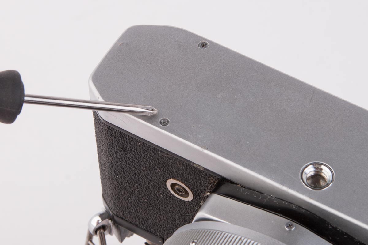
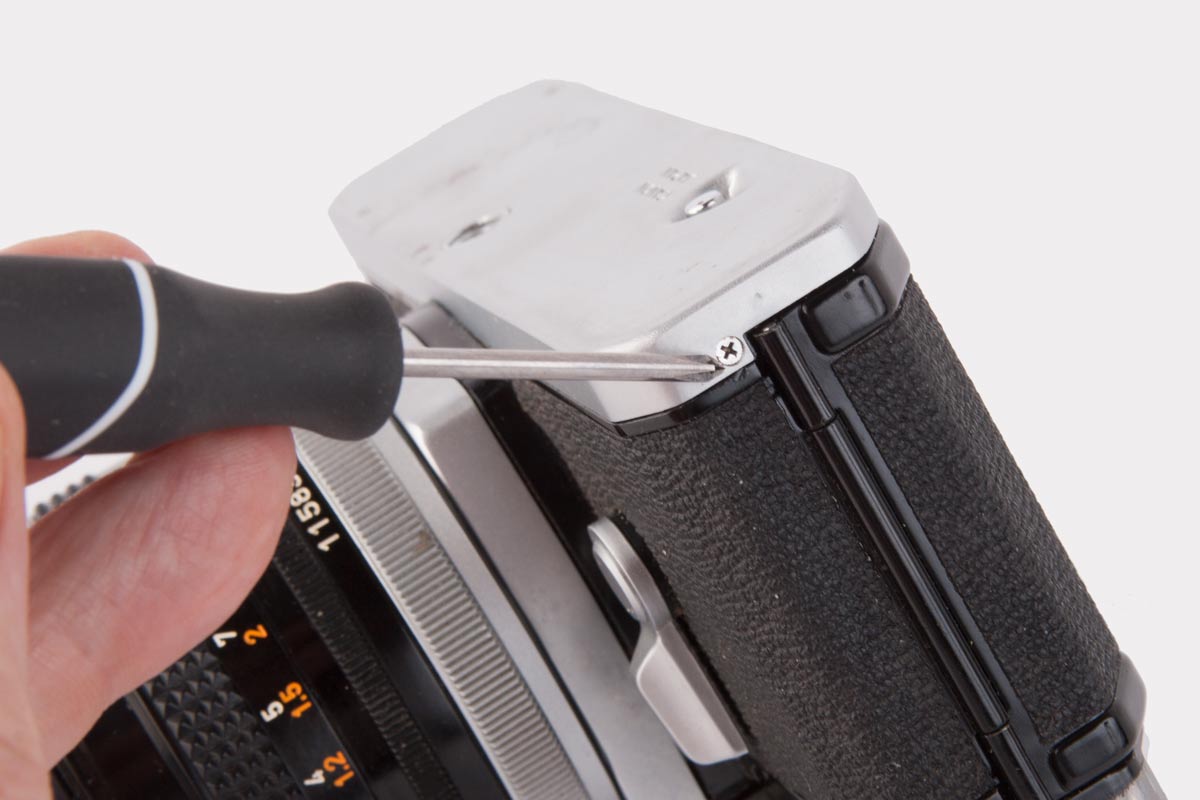
The final step to removing the top plate is to remove the small screws on the skirt: one in front, one on the right end, and two on the back.
9.
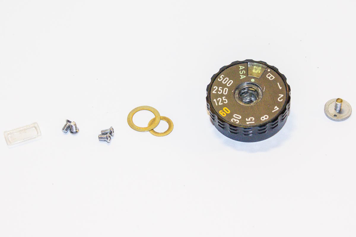
And here are the final pieces we have to save. On the left are the four small screws. The rest is from taking the shutter dial off.
OK ….. so now what? Well, we take the top off. It is a close fit and requires some wiggling and careful prying but it will lift off now. The red wire is for the hot shoe on the top plate. The signal to the flash travels through this wire. We unsolder it to completely remove the top.
Before we start to figure out what all is in here, we now take off the bottom plate as well. This will be a lot easier.
10.

Removing the Bottom Plate
11.
To remove the bottom plate we must remove the two screws in the bottom plate.
12.
Then we take out the screw in the bottom plate by the hinge for the back.
13.

Once the three screws are out, the bottom plate lifts off easily.
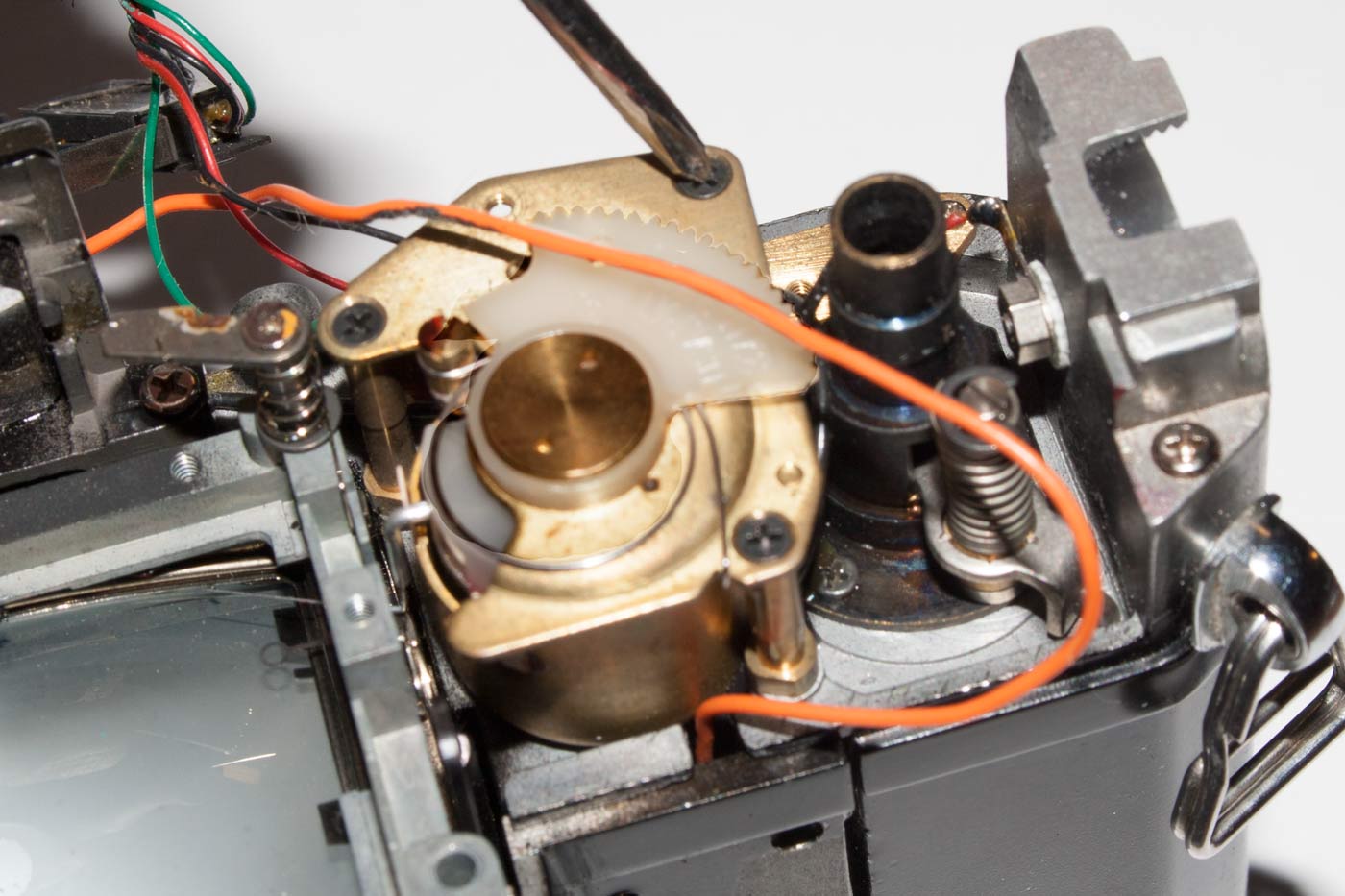
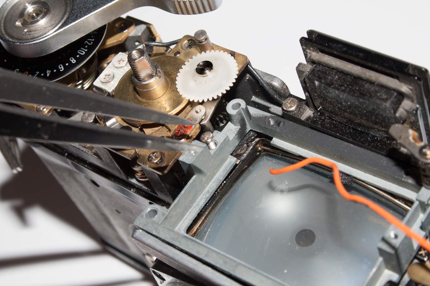
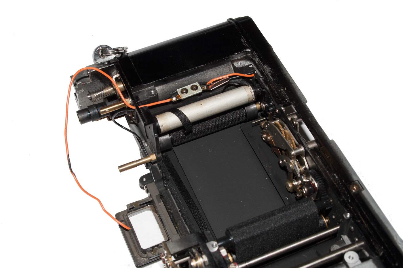
The bottom plate comes off without any difficulty as we shall see. However, when you turn the camera upside down for this operation there is a plastic gear that falls of the shutter speed post. You can see it clearly pointed out in Picture 14. This gear appears to transfer movement in the shutter speed dial to the toothed bar that runs across the top back of the camera as shown in Picture 15. This bar communicates shutter speed information to the exposure “computer” on the left side of the prism.
14.
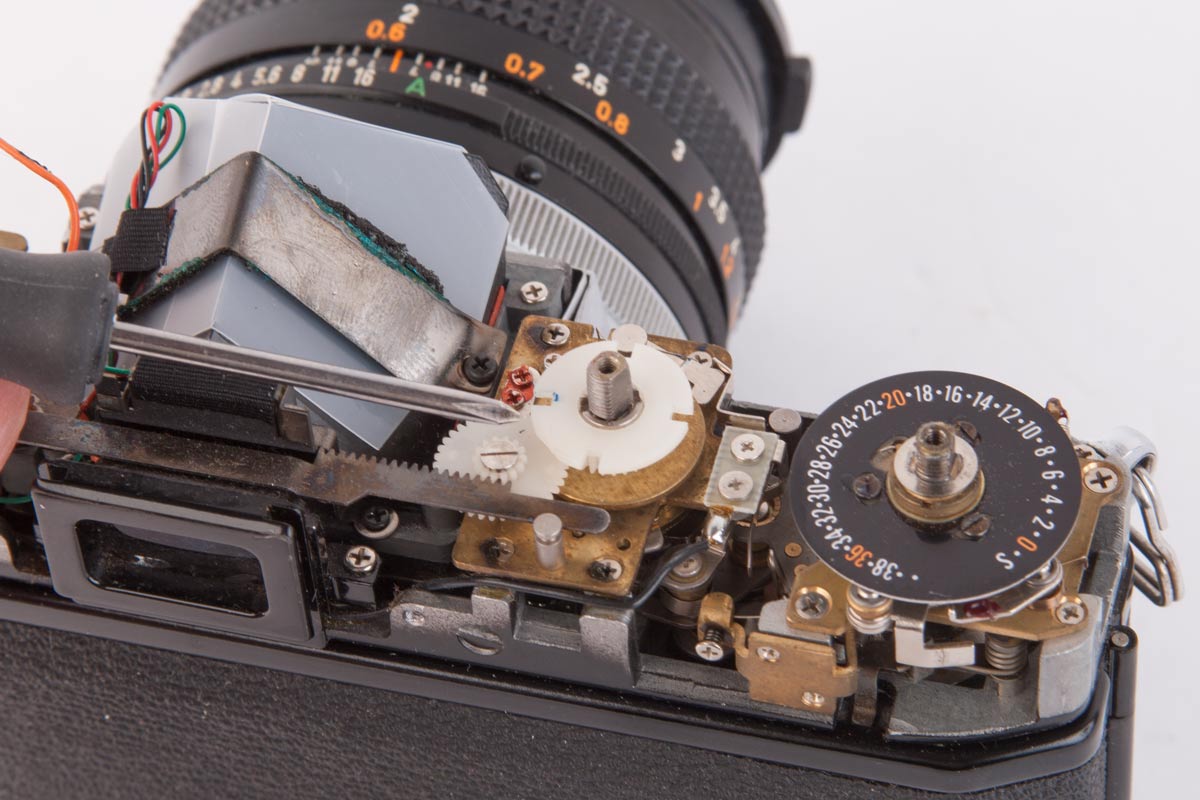
The white plastic gear on the top of the Shutter Speed Post lifts off. You can see that it transmits movement of the shutter speed wheel to the horizontal metal toothed bar that passes over the top of the view finder window.
16.
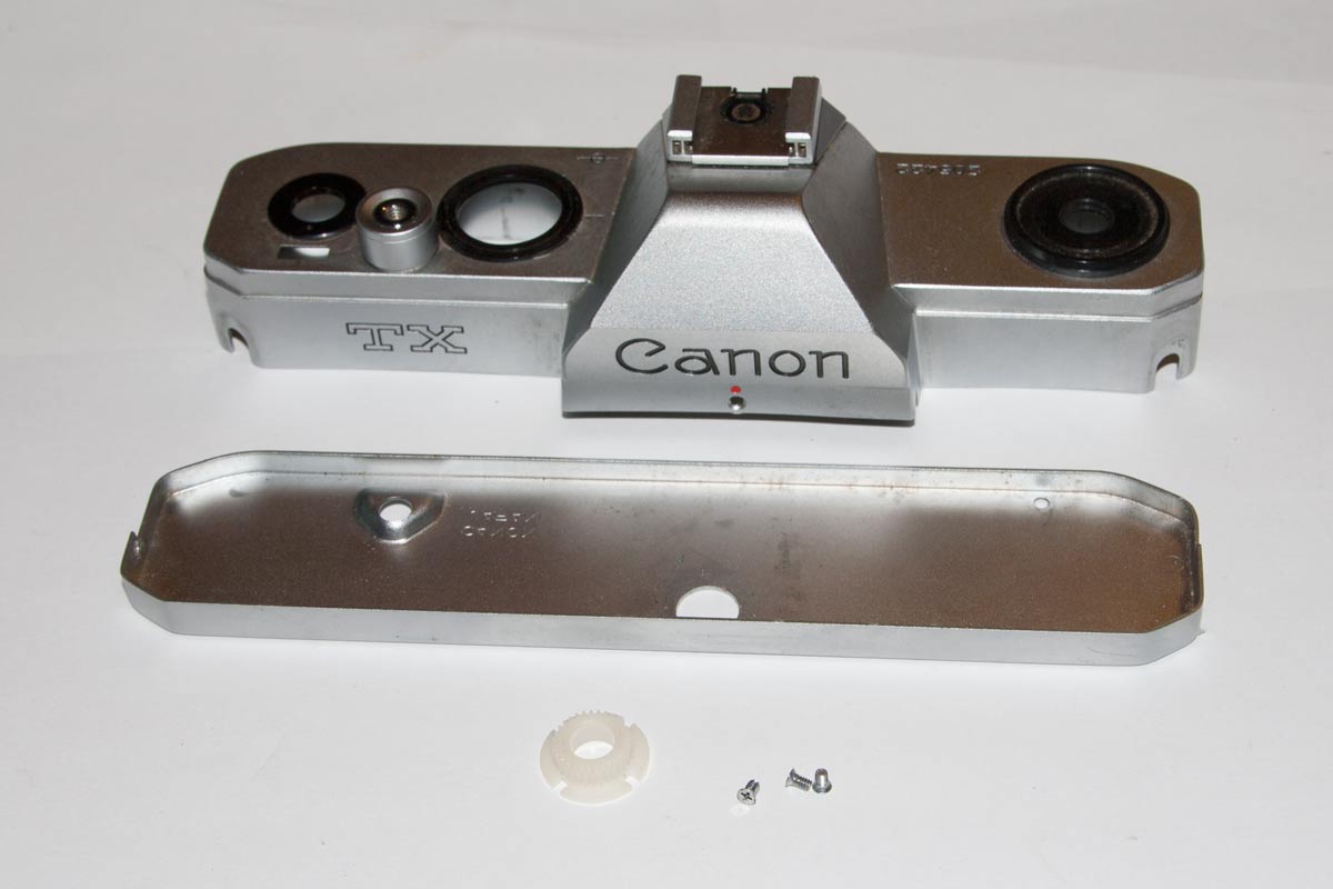
We now have the Top and Bottom Plates off. At the bottom we have the plastic gear from the Shutter Speed Post and the three screws that secured the bottom plate.
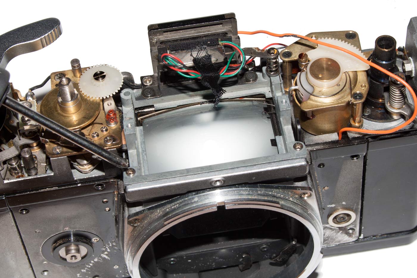
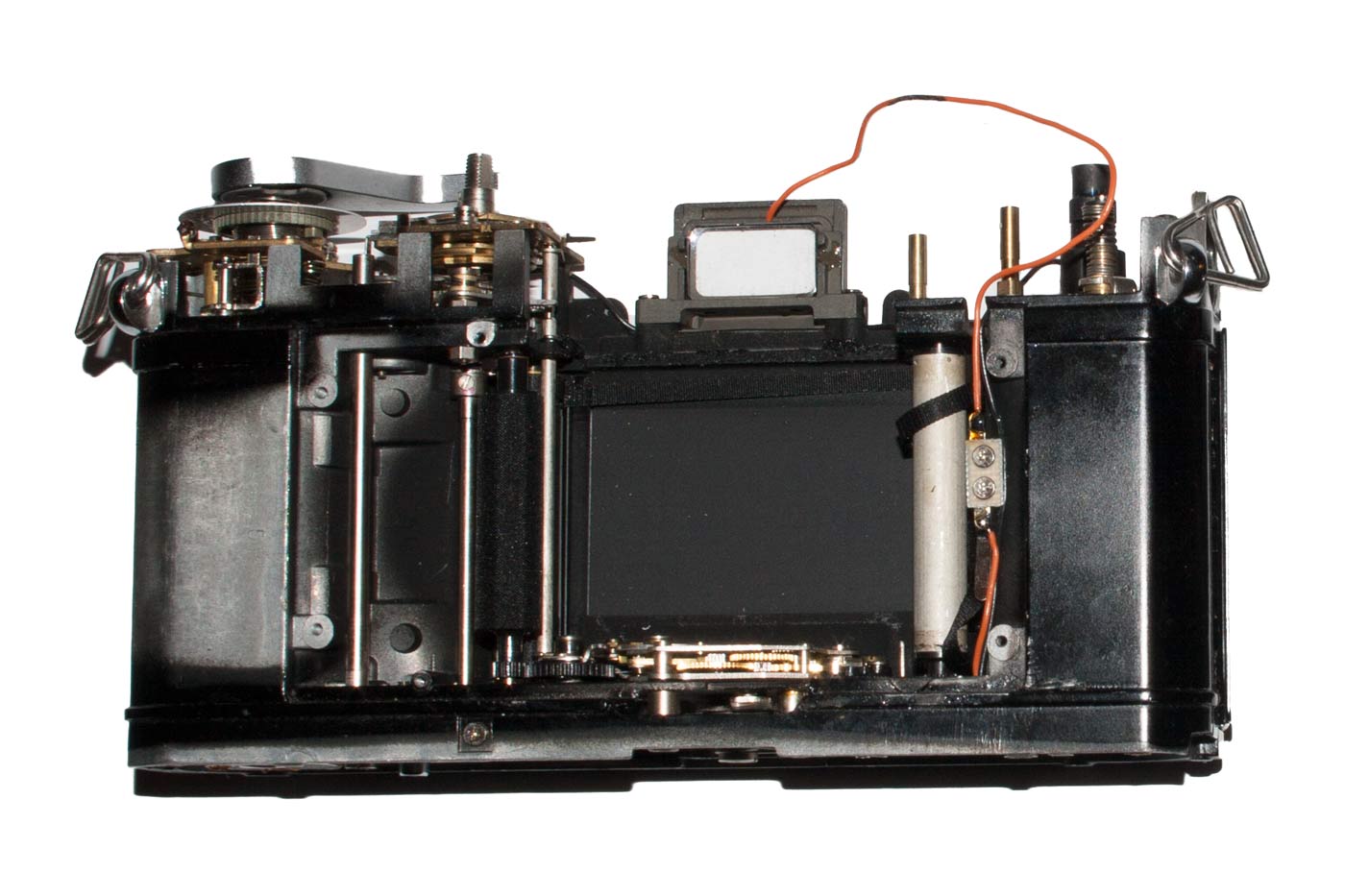
15.

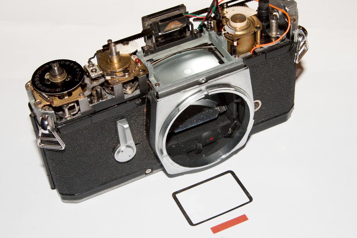
In this image the toothed metal bar is clearly visible as it passes over the view finder opening. The exposure “computer” is on the left side of the prism.
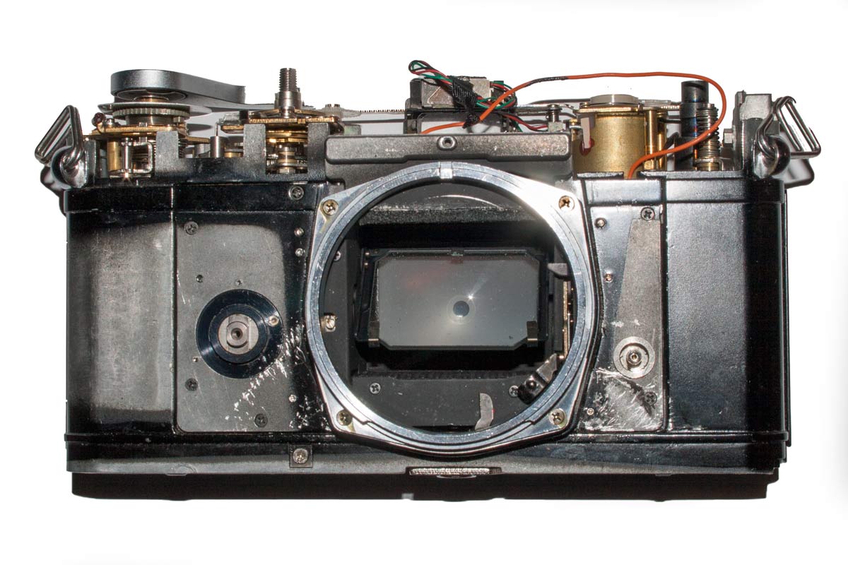
So there we are: top and bottom removed so we can see into this camera. Why the shutter has not been firing is still not clear so we will have to examine how this should work and then maybe we can see why it does not work.
To get into the camera further I think the Prism is the obvious next target. It may not be essential to the repair, but this is also a voyage of exploration.
Removing the Prism
You can see in Picture 15 that the prism is secured by a strap across it and the strap has a screw in each end. The prism is painted black and it has a cover of white plastic to protect it.
Removing the prism is a simple matter of removing the two screws in 15 and lifting the strap off. Remove the tape holding the Red, Green and Black wires and lift of the white plastic cover. Then gently raise the prisim and lift out. This prism is a delicate optical lens with surfaces that can be marked easily. Handle it only by the black areas where the glass is protected.
17.

The prism, its plastic cover, the strap and two screws.The black strap that holds the prism in place is foam backed. The foam was badly deteriorated and crumbling. On reassembly it will have to be replaced.
19.
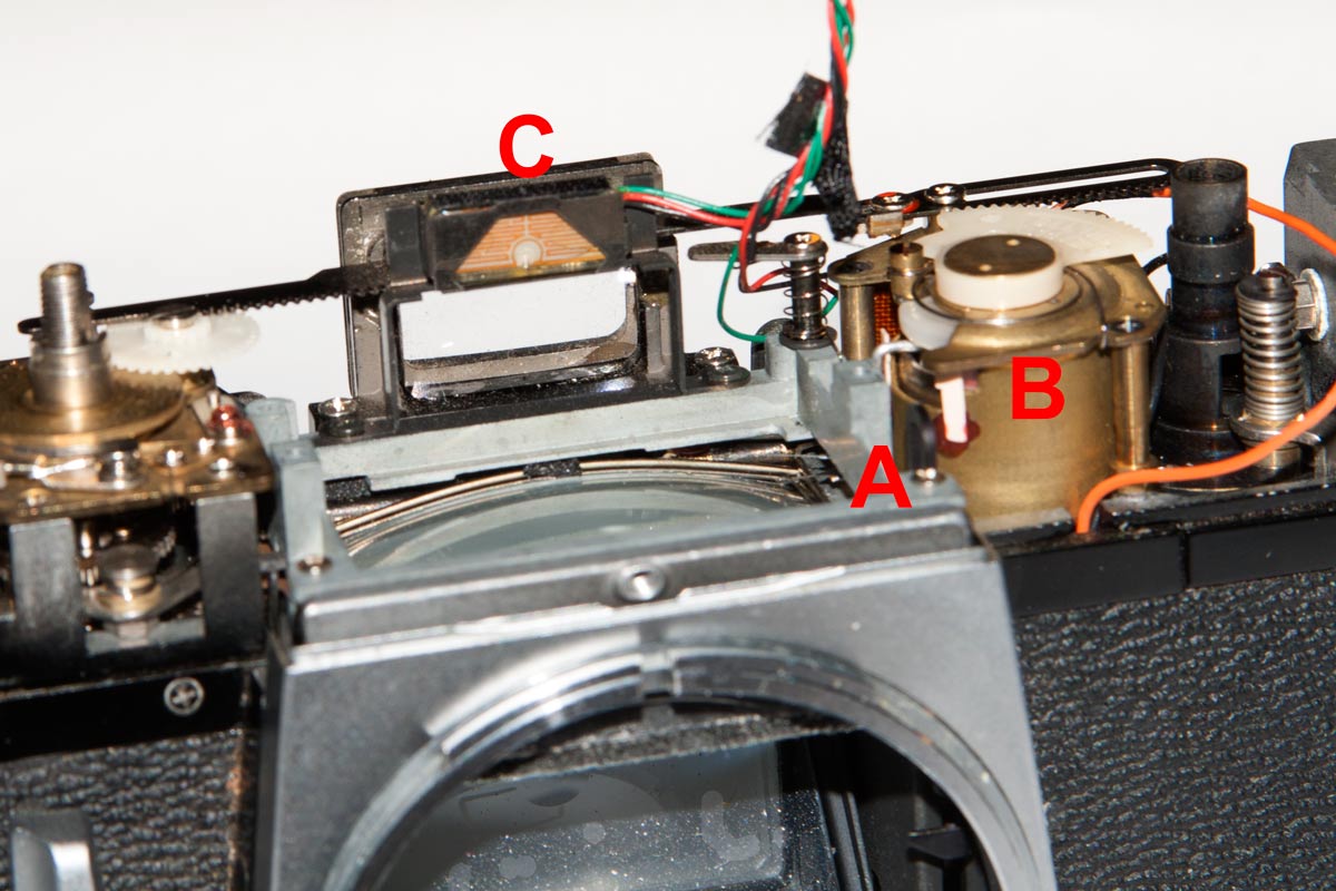
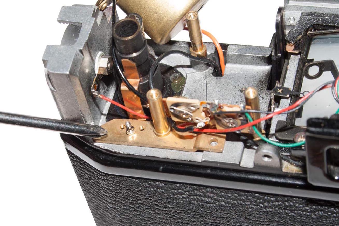
The same lettering is applied in this view but we have a clearer view of the light sensor at “C” and the Red, Green and Black wires that are attached to it.
18.
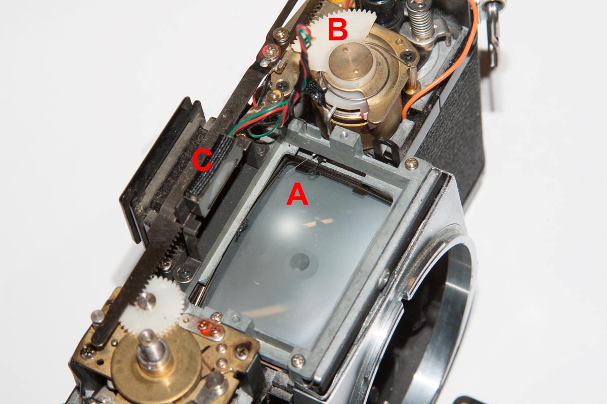
At “A” is visible the two needles that must be matched to acheive correct exposure. VERY DELICATE! “B” is the exposure “computer” and “C” is the selenium cell light meter.
20.
When the prism is removed there is a metal frame and small pink card sitting on the ground glass. These should be removed gently with tweezers.
And we have removed the prism. Now it is time to delve a little deeper and find out why the shutter will not fire. But first, we have to figure out how it works. That will require a combination of exploration and research.
9 December 2016 – Finding the Problem
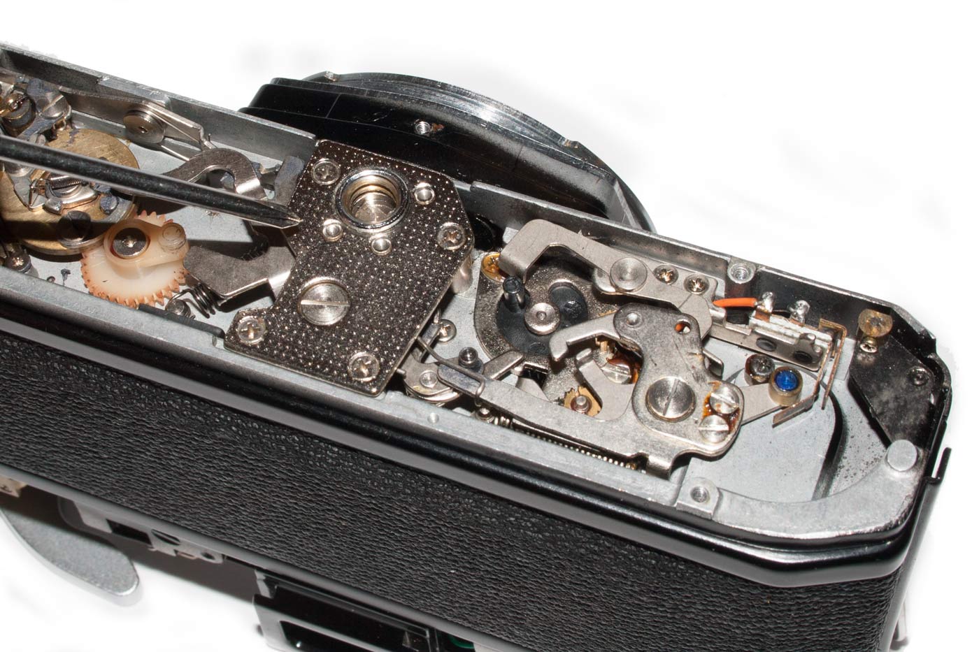
So, having got to this point I have had time to examine our victim. I took the bottom off a functioning TX to compare them and found that our specimen does not work the same. The mechanism on the bottom does not move at all like the good copy. And I can see nothing obvious that would explain it. So we have to dig deeper. I want to get into the shutter mechanism and that means taking out the Mirror Box.
But the deeper we go, the less chance I will ever have of reassembling this as a working camera. But I am learning a great deal as we go and I am so impressed with the complexity and ingenuity of this camera. Compared to today’s cameras, this one is simple, but it is great for learning. Almost everything is mechanical and so I can see and study what is going on.
So, on to the Mirror Box.
21.
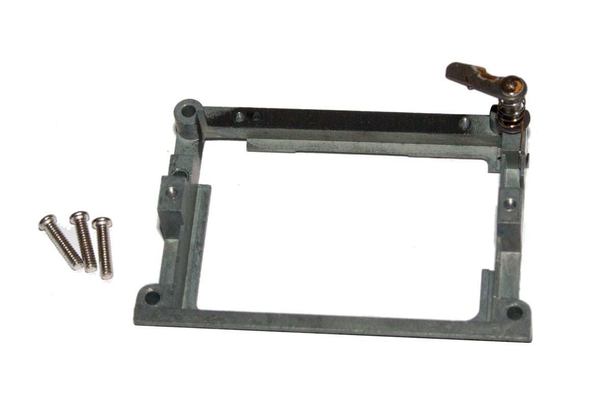
The next thing to go is the tripod attachment which is the heavy metal plate in the bottom held in by four screws.
23.
Then we have to remove the Diaphram Release Lever. If we don’t it will hang up on the mirror box.
22.
Taking this out was easy and I think even I can figure out how to put it back.
24.
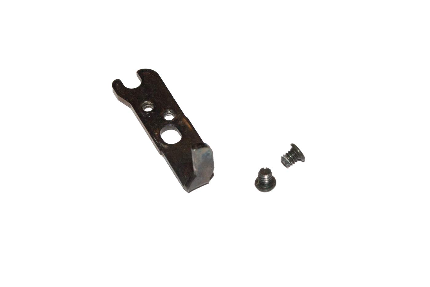
The removed Diaphram Release Lever with its two mounting screws.
The more we get out of the way the more we can see and understand. So I think the electronics are next. In this camera we are not talking about anything too complex as you shall see.
There was no particular order here so don’t get confused if I seem to be wandering.
25.

The toothed bar across the back comes out easily.
28.
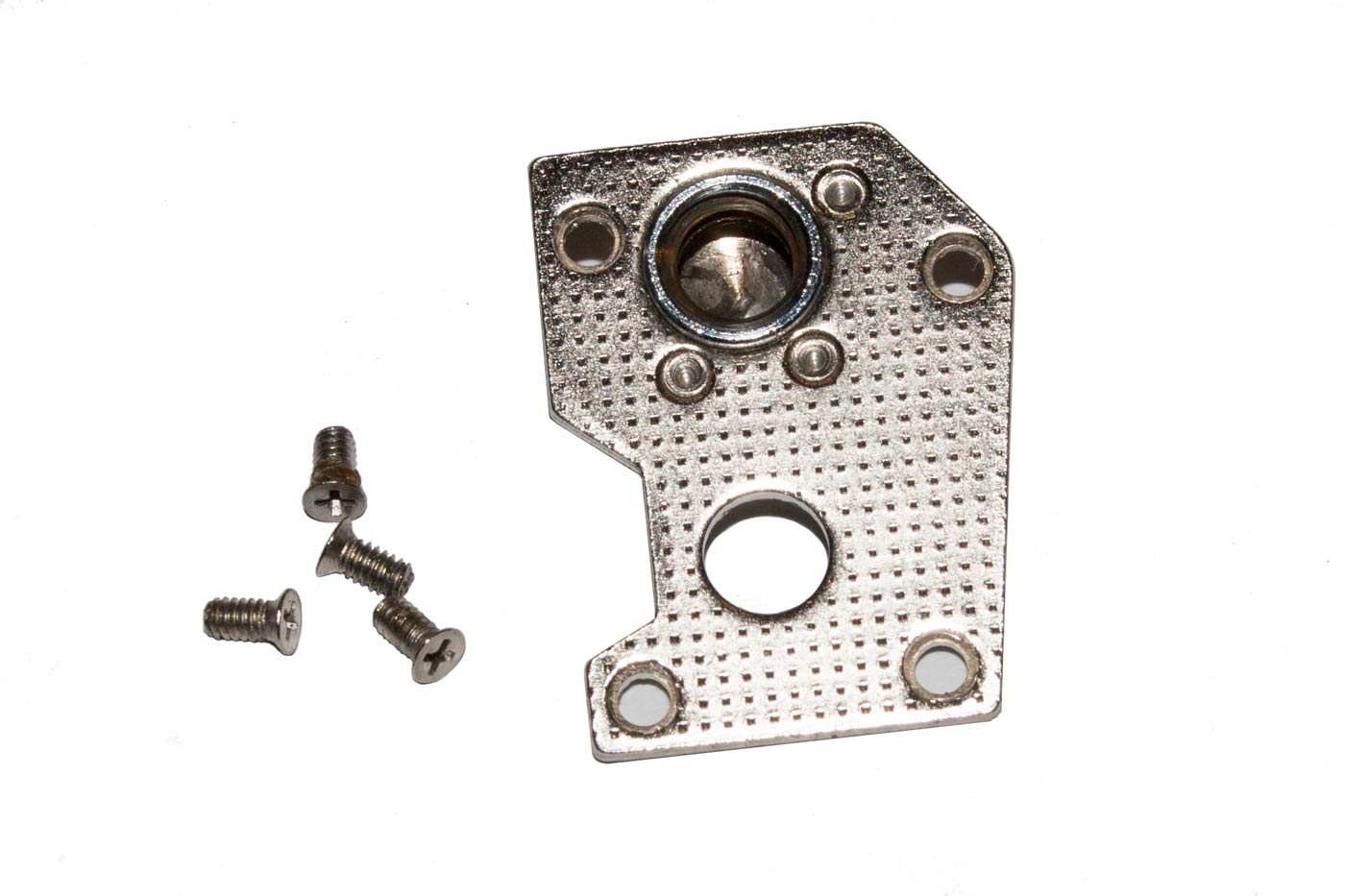
The light meter assembly unscrews easily as well.
26.
There is a bezzel around the focusing screen.
29.
The bezzel after removal with its three screws.
27.
Remove the screws holding it in place over the screen.
30.
Finally the brass attach point is unscrewed.
31.
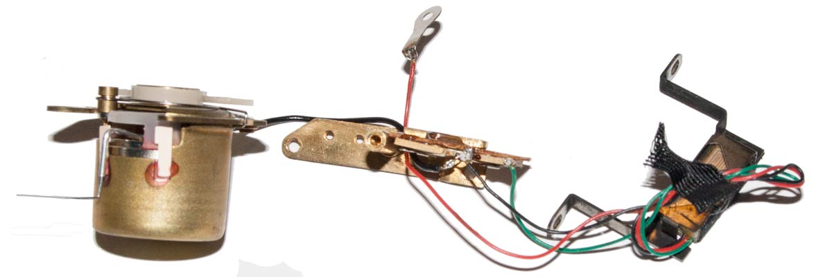
This is the total electronic circuitry in the TX. Not much by today’s standards, is it?!. We put it aside for now but we’ll come back to it later and try to understand it.
The screws that hold the Mirror Box in the body are under the leatherette. I have never tried removing the leather on a camera, or replacing it for that matter. So this will be interesting.
32.
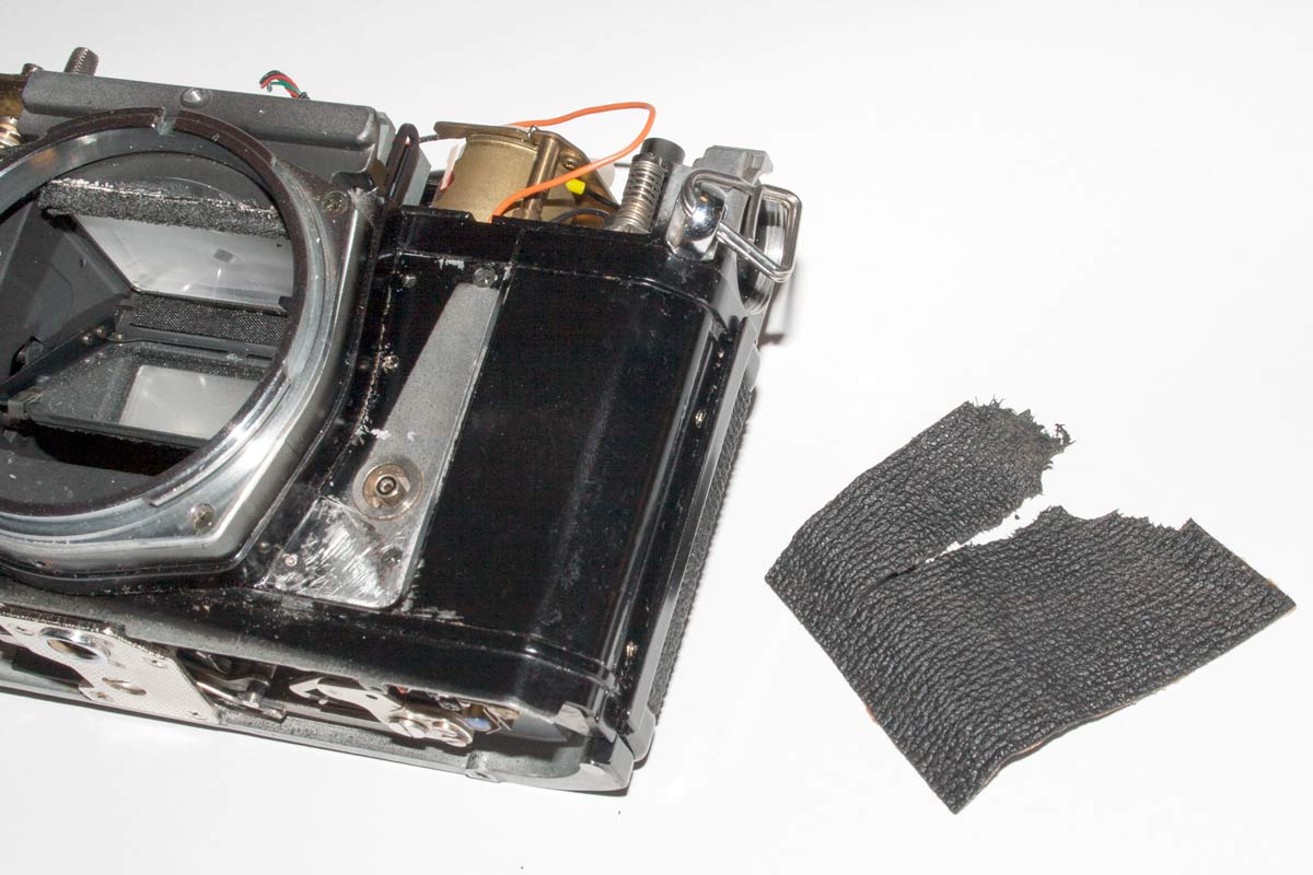
The leatherette did not fare well as you can see. It ripped as I tried to remove it.
Getting a small screw driver under one edge of the covering was not difficult and some of it did pull back. However I quickly ran into glue that would not let go. I tried solvents, alcohol, water, degreaser, even “Goof-Off” which is a dangerous one to use because it will dissolve plastics. Nothing worked. I tried being gentle. No luck. Finally I simply used brute force (always a bad option) and it came off.
Underneath I found the body marked with someone else’s attempts to remove the leatherette. I assume they failed because the camera was never repaired. But you can see the scratches in the bottom left part of the body that was under the leatherette.
33.
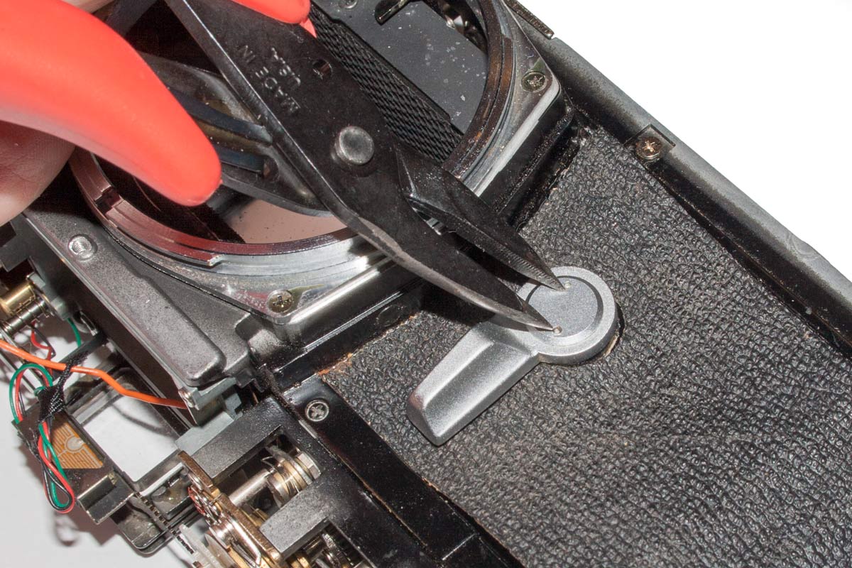
For simplicity, it is easier to remove the self timer lever than try to remove the leather with it on.
35.

With a small screw driver we gently raise a corner of the leatherette.
37.
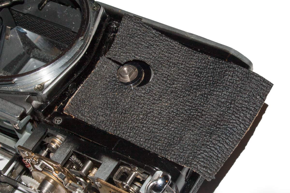
The leatherette came free without apparent damage. We can probably reuse it.
34.

The lever comes off easily. It is held on by a simple screw and nothing more.
36.

Gentle steady pressure was enough to free the leatherette from the body.
Taking the leatherette of the other side was a totally different experience. I lifted one edge and the piece pieled away with no trouble. It was firmly attached but it came away clean, as you can see.
I wonder if the first side had been partially removed and then stuck down again with a tougher glue. There was something different happened there. However, here we are, with the covering off. I will be faced with finding new covering material when we put all this back together again. I have been looking at second hand purses and boots in the thrift shops about and there is lots of likely material. Should be fun when we get there.
38.
39.
The screws holding the Mirror Box in are now easily accessible.
40.

The front of the Mirror Box out of the body.
41.

The back of the Mirror Box with the mirror still in place.
42.
At last, the back with the shutter mechanism laid open for us to examine.
43.
That is strange. What are these unattached straps laid over the white roller?
44.

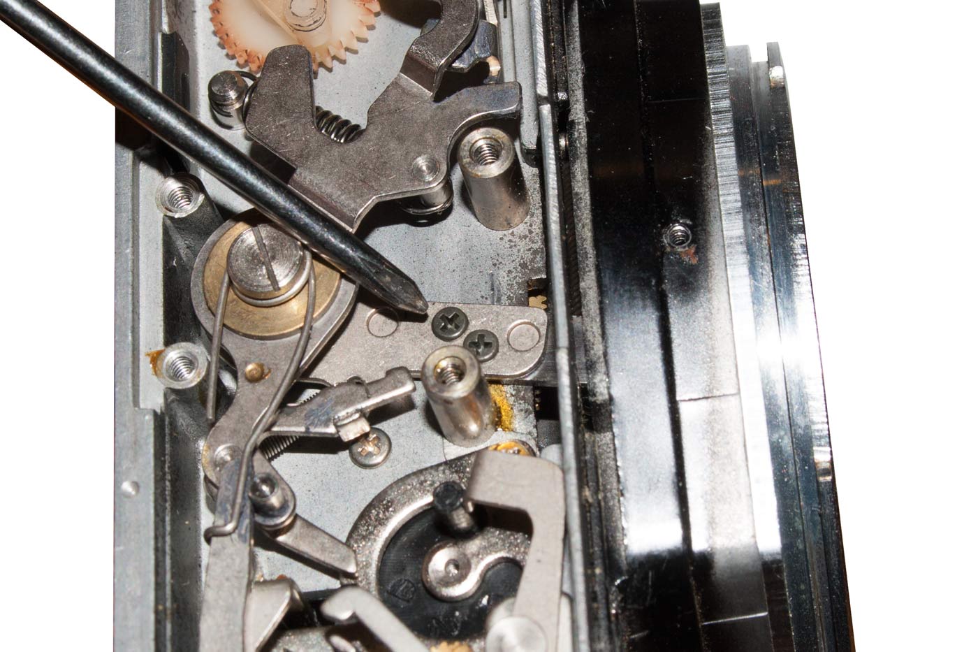
And here at last we have found the problem. One of the shutter curtains is not connected to the take-up spool. The spool provides tension and the power for the shutter to fire. But it cannot function in this condition.
Well, this has been a long post. We have plumbed the depths of the TX. It lies before us in disarray. But the challenge now is obvious. To understand, to fix, to reassemble and, at last, to use it to take a picture.
However, enough for this post. We shall start anew with the tale of the “Return Journey from Chaos”.