I acquired a Canon Photura camera with which I have been preoccupied for the last several days. A really interesting and somewhat curious machine. But that is not what this story is about. It’s about wanting to shoot some film with the camera.
My bulk loader contains Ilford HP5 with a nominal ISO of 400. But reading the Photura manual I see that the camera needs film with DX Codes to set the film speed or it defaults to ISO 25. Oh, and my reusable cassettes are black plastic, not metal. So how to use this camera with the assets at hand? That is what this story is about.
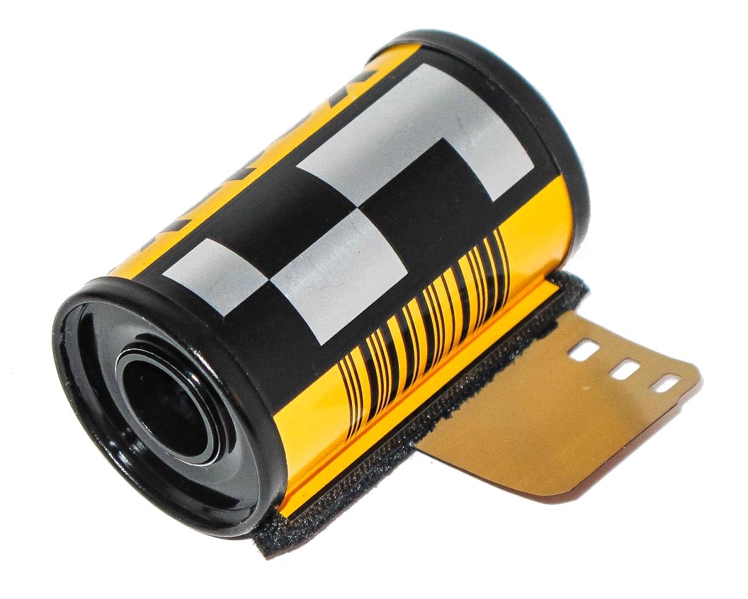
On the 135 film can one can see the normal linear bar code next to the film slot. This is read by the automatic film developing machine at the film lab. On top are the larger squares of the DX code we are familiar with which are read by the camera. There are actually 12 rectanglular areas of two rows of six.
The DX Code
The DX codes are the black and silver squares on a 35mm cassette and I knew that some cameras read them to tell what film was being used. But when I started to dig into the real story I found it more complex than that. And very interesting.
DX comes from Digital IndeX. The codes are both ISA (International Imaging Industry Association) and ANSI (American National Standards Institute) standards. The code system was originally introduced by Kodak in March of 1983 for marking 135 and APS film and cartridges.
As cameras were becoming increasingly automatic a way was sought to allow the cameras to read information about the film directly from the film can thus eliminating the need for setting the film
speed on the camera. But it went further than that, as we shall see.
Fuji had a speed encoding system as early as 1977 based on electrical contacts on the film can. However, their system did not catch on but it was a start. Kodak came out with their system in 1983 on their 135 Kodacolor VR-1000 film. The first cameras to make use of the new coding were the Konica TC-X SLR, the Pentax Super Sport 35 and the Minolta AF-E. The concept proved very popular and it spread rapidly and quickly became the industry standard.
On the bottom edge of the film one can see a bar code. Actually it is two bar codes one above the other and there are a different set of codes for each frame of the film. These codes are used primarily by the photo printing equipment.

We have a Newsletter
There is a Newsletter for thecanoncollector.com to keep you up to date on what we are posting. Try it!
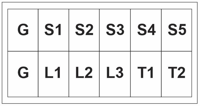
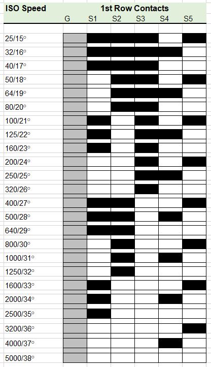
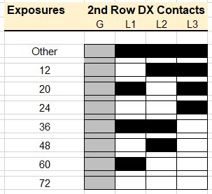
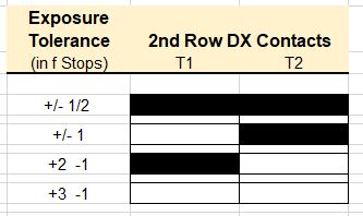
The CAS Code is composed of 12 rectangles on two rows. This diagram shows the rectangles looking at the can with the film slot at the top. The two rectangles on the left are always bare metal. The other 5 in the top row, S1 to S5 carry the film speed. L1 to L3 tell the film length and T1 and T2 indicate the exposure tolerance of the film.
S1 to S5 Film Speed
Using this chart one can decode S1 to S5 which are the film speed part of the CAS Code.
L1 to L3 Film Length
T1 to T2 Exposure Latitude
Film Edge Barcode
First, it is included as a latent image on the edge of the film and is developed when the images are processed. There are actually two bar codes, one on top of the other, for each frame on the film. Because these are not seen until after the images are developed the codes are used mainly by the photo printing machines to identify the film and align the images for printing. They include information on film type, manufacturer and frame number.
Cartridge Barcode
Secondly, by the film slot on the cartridge there is a regular linear barcode which is scanned by the processing machines to ensure that the film is the correct type for the process being used.
Camera Auto Sensing Code
And finally there is the DX Camera Auto Sensing (CAS) Code we are familiar with: the black and silver squares on the can next to the bar code. This is what the camera reads. And this is where the answer to my problem lies. So how does it work?
The CAS area is composed of 2 rows of 6 rectangles, for a total of 12, which are either bare metal of the film can or over printed with black paint. An electrical contact on a silver area will be grounded and if it is on the black paint it will make no electrical connection. The camera has electrical contacts positioned in the film chamber to read where the black and silver rectangles are and thus know what the CAS code says.
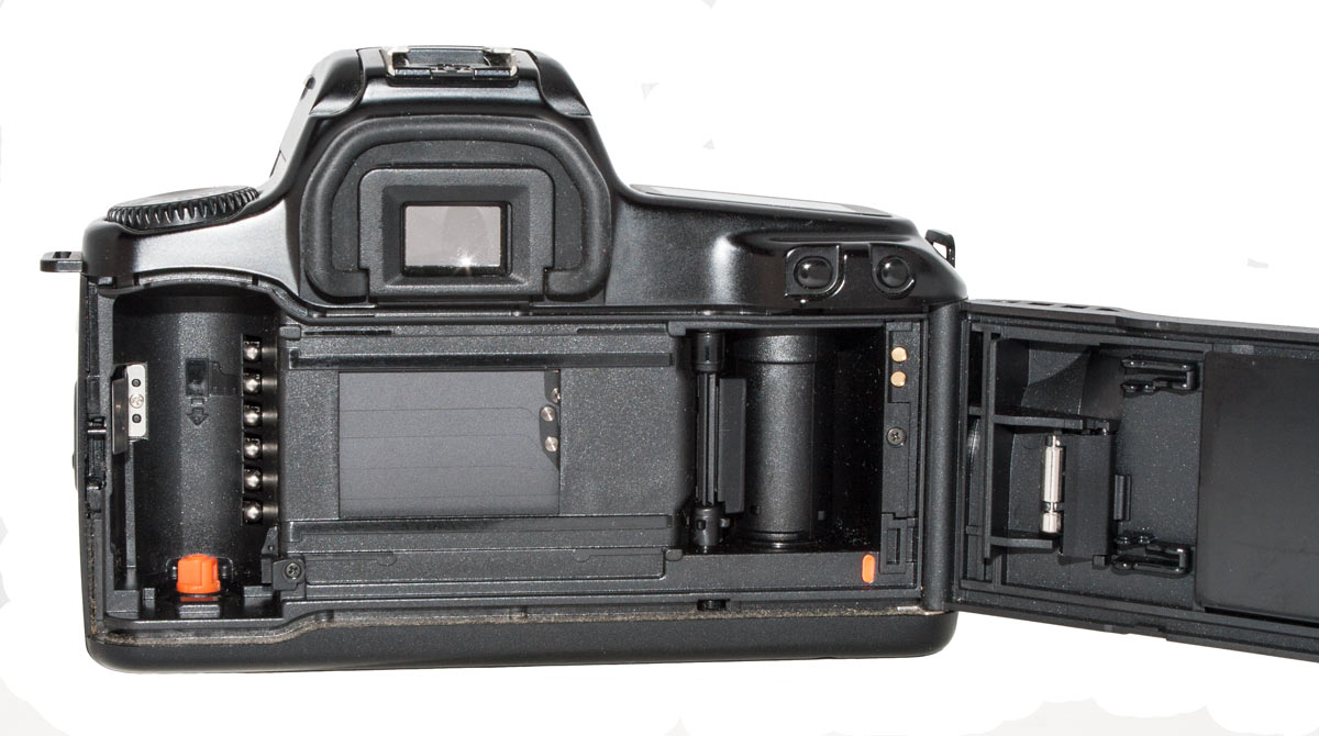
Cameras do not usually read all of the information. Some have up to 10 electrical contacts and some as few as three.
The electrical contacts for reading the CAS Code are clearly visible in the film chamber on the left in this EOS SLR.
Creating a DX Label
So, armed with this information I was able to tackle the problem we began with: how do I apply DX Codes to a plastic reusable film cartridge? It was obvious that I would have to create a label to glue on the cartridge.
Looking at the codes on the left of this page I could see that S1 to S5 for ISO 400 would be Black, Black, Silver, Silver, Black. The rest was really not important as all I wanted to do was set film speed.
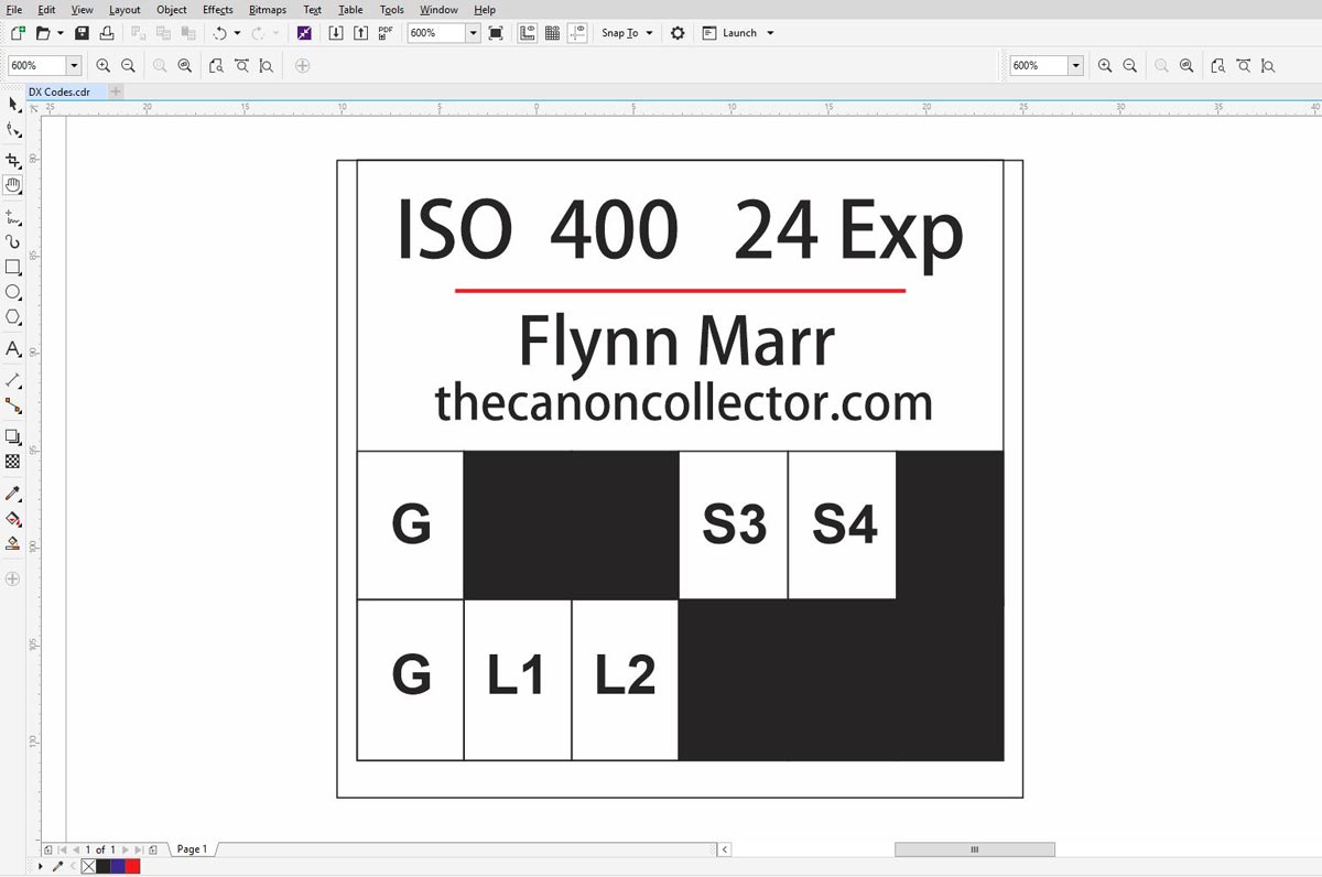
The first thing I did was carefully measure the CAS code area on a commercial film can to make sure that I would position my Black and Silver rectangles correctly. With these measurements I turned to my computer to create a label. My program of choice was Coreldraw but any similar program would work. I could have done it in trusty old Photoshop but I find Corel easier for this type of text heavy label.
A screen shot of the label I created in Coreldraw. The rectangles can be colored as desired but any that are not black will be cut out leaving a hole in the label.
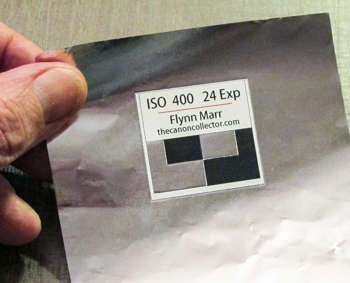
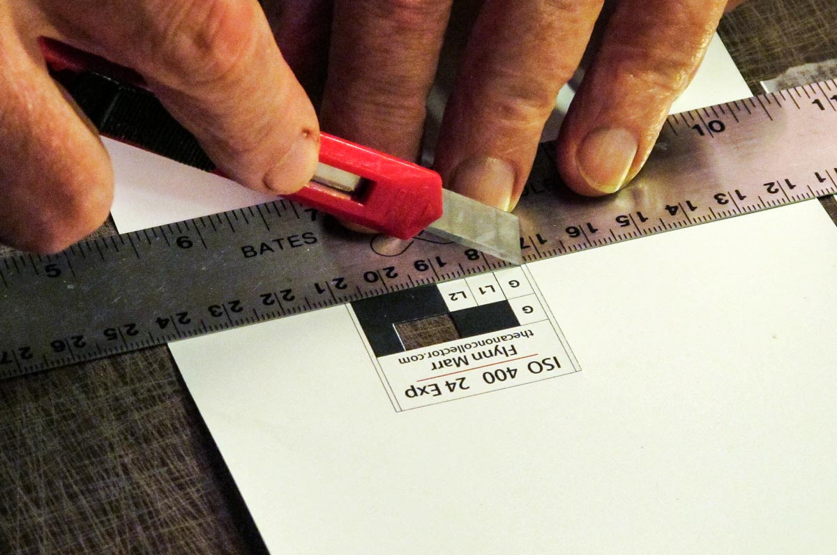
Once the label was cut out and the non-black rectangles removed the label was glued onto a sheet of kitchen aluminum foil.

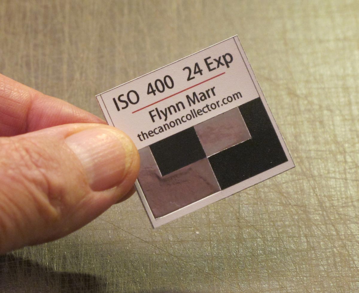
And here is my
finished and DX Labeled film
cartridge. The label was designed to fit right
up against the film slot and was just the right size to correctly
position the CAS code area. Although the “can” is made of plastic the
aluminum foil provides the electrical contact necessary for the label to correctly
instruct the camera that the film speed is ISO 400.
This website is the work of R. Flynn Marr who is solely responsible for its contents which are subject to his claim of copyright. User Manuals, Brochures and Advertising Materials of Canon and other manufacturers available on this site are subject to the copyright claims and are the property of Canon and other manufacturers and they are offered here for personal use only.


