Old cameras are not worth a great deal in most cases. I am buying FT’s and FTb’s at US camera shows for $5.00 to $10.00 dollars. It makes no sense to have them serviced when you can acquire them so cheaply. Even paying $100.00 for a camera does not make repair economical. If I want them fixed the only rational route is to do it yourself.
I have been buying tools and slowly digging deeper and deeper into the inner workings of some of my cameras. Some repairs are simple: I have replaced light seals and freed stuck iris blades and removed fungus from lenses. It is a slow process but I am learning (and in the process reducing a few cameras to an assortment of parts).
Focal plane shutters can have any one of several errors. One is called Capping (also called Tapering) where the two curtains do not move at the same speed. Typically the second curtain moves faster than the first and catches up to it as they cross the film. The film is correctly exposed on the first edge of the frame but as the curtains move the exposure reduces and by the time the gap reaches the end of the frame the exposure is reduced substantially making for an uneven image, side to side. The shorter the exposure, the more critical this becomes. Capping can be caused by weak tensioning, dirty or dry lubrication or a variety of magnetic selinoid problems. It can occur as Openside or Closed Side Capping.
Another problem we can encounter is called Curtain Bounce which happens when the curtains collide at the end of their travel causing a momentary wrinkle which can often allow a momenty light leak.
At some point I am going to tackle shutter repairs and for this a shutter tester is necessary. So I have been reading on the Net about building my own shutter tester. I came up with the schematic on the left and a brief description of how it worked and it seemed pretty straight forward. OK, I have to be honest here. I have a University degree in physics which had a strong emphasis on electronics and I have worked briefly in an electronics research lab for the Canadian government back in the 1960’s. So soldering up circuits holds no terror for me. And this is a pretty simple affair.
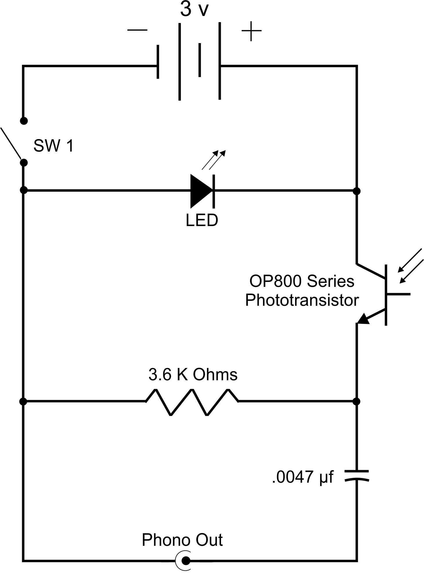
Let’s go through it. The three volt battery is simply two AA cells. The switch has an obvious purpose. The LED (light emitting diode) is simply a light to tell you the device is on. It makes no noise and you could easily leave it on and run your battery down.
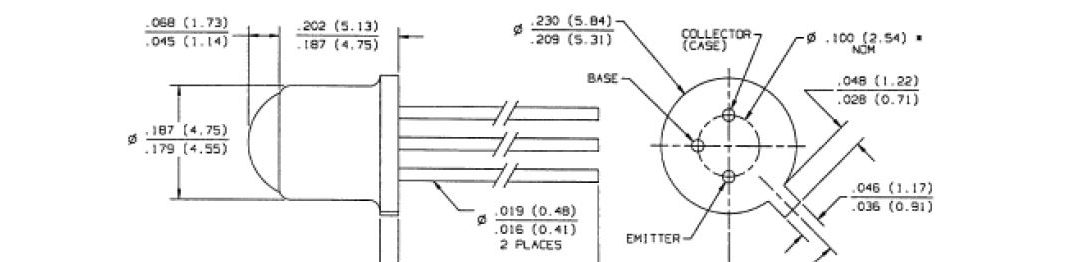
The phototransistor is the heart of the device. It is in a case with a window in the end and the more light that
falls on the emitter junction the more current the transistor passes. If it is in relative darkness and is then hit with a blast of light (i.e. the shutter opens) current suddenly flows. Similarly, when the light suddenly disappears, the current stops. (the spec sheet for this phototransistor is here)
Current flows through the 3.6k ohm resistor and when it increases the voltage across the resistor goes up. This increase in voltage is passed through the .0047 microfarad capacitor as a pulse of voltage which quickly leaks away through the sound card input. When the voltage suddenly drops back to its normal level a pulse in the other direction passes through the capacitor.
OK, so far so good. But what about this Sound Card that has crept into the conversation? Well, that’s how we measure the timing. We plug the device into the microphone input of a computer sound card. Then we capture the waveform in a program like Audigy or Cool Edit which are both available on line for free. They will look at the output of our tester as a sound file and display the waveform with a time scale so that we can calculate how long the pulse of light was. Of course, that pulse of light lasted as long as the shutter was open and no longer.
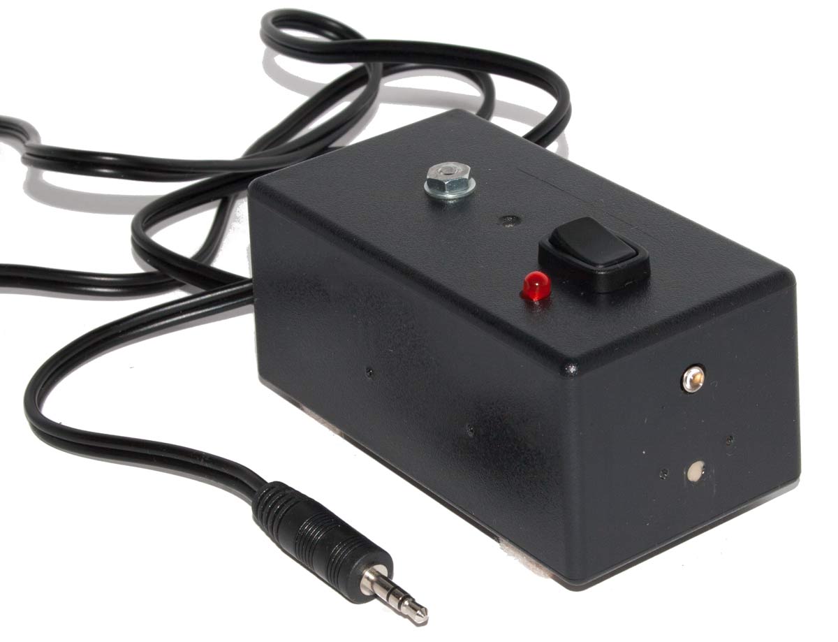
This is the completed tester. The on-off switch is on the top and the indicator light, the red one, is beside it. The phototransistor is the small button on the front (the top one).

By any standard the job inside the box is a mess. I will do better next time. You can see the two AA cells and the resistor and capacitor. The wire out is an audio cable that I butchered.
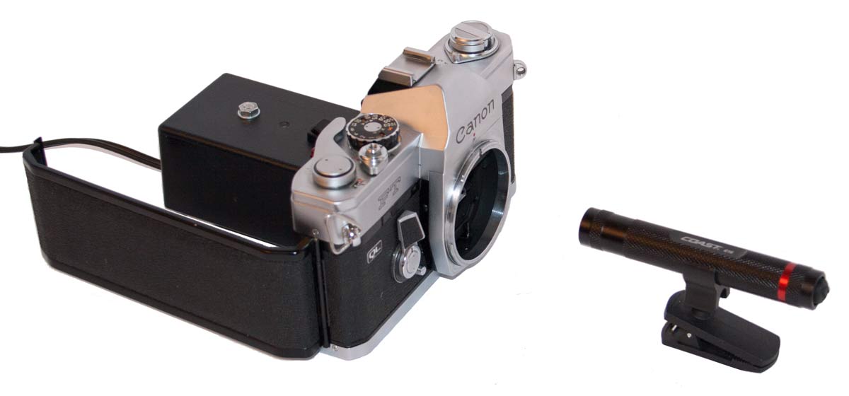
This is the test setup. Light level in the room should be low but not dark. The phototransistor is placed behind the camera’s open back up close to the shutter curtain. In front of the camera is a small LED flashlight I bought at my local hardware store for a few dollars. Nothing special there. Turn the tester on, turn the flashlight on, cock the shutter , begin recording the sound input and fire the shutter. It is that simple.
So what do we get on the screen. Now, in truth, it was not as easy as I have said and I had to do a little adjusting here and there. I reduced the voltage to 1.5 volts (a single cell) and I played with the sound card input levels. But in the process I learned a lot.
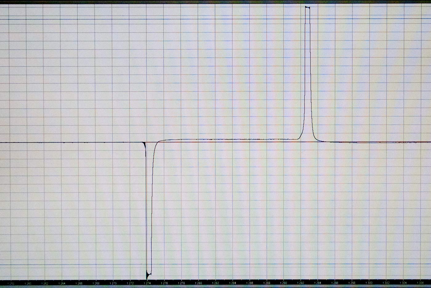
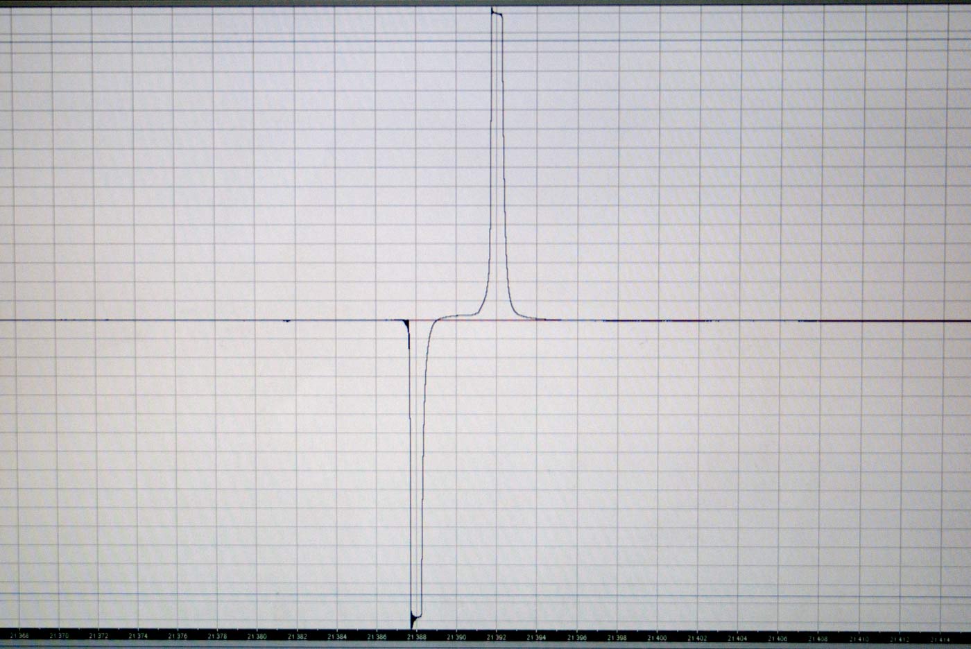
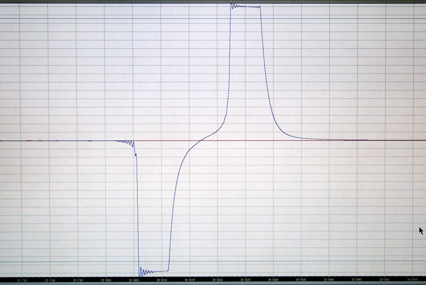
Below are three images. On the left is a shutter speed of one fiftieth of a second. The time scale is visible at the bottom (not very legible in these images) and time is running from left to right. In the centre is one five hundredth of a second and on the right is one one thousandth of a second.
When the shutter opens the pulse is down. When the shutter closes the pulse is up. The width of the pulse is the time it takes the pulse to die away through the sound card input impedance. Notice that as the shutter time gets shorter the pulses move towards each other and at the one thousandth setting they are beginning to interfere with each other. This tester cannot measure a higher speed. However, it can measure right down to a one second shutter speed.
It is possible to check for “capping” by placing the tester at the left edge of the shutter curtain and taking a measurement and then placing it at the other edge and taking a second reading. This way you will see if the exposure times are the same on both sides. Of course, just holding the camera up to a uniform light, without lens, and watching through the shutter as you fire it at high speed will reveal severe capping.
The math is easy. Subtract the lower (left) reading from the higher (right) reading. You will get a number like 0.018, say. Then divide one by this decimal number. In this case the result is 55.555…. . The shutter speed is one fifty fifth of a second. You never get exact speeds. But this is so close that you will never detect the discrepancy in your images.
The pulse images are wide. Just make sure to measure time at the same position on both pulses. I was extending the front edge of the pulse to the baseline and taking that as my time. What you seek is uniformity of technique to give you consistent results.
So that is my adventure with shutter speeds. I have more work to do with this, I want to build a new tester that gives me narrower sharper pulses which will give me more accurate times.
But really, when all is said and done, how important is it that a camera in a collection continue to function? Surely you want examples of each type that are in the best condition you can find. Repairing them can degrade that condition. And all of these cameras will cease to function at some point. So I will chose a mint condition non-functional camera over an excellent working example. Actually, I would probably want both so I could try using the camera a few times. Then I would part with the excellent copy and keep the mint.