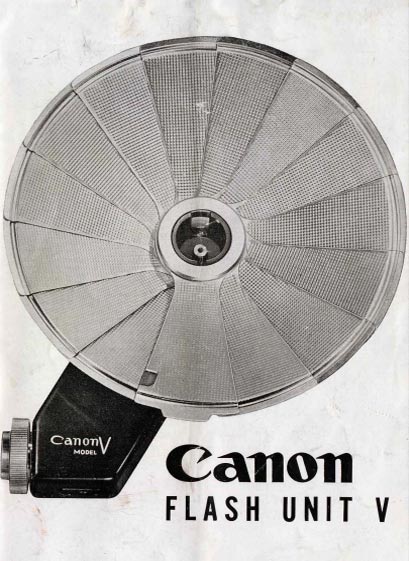
Flash Unit V
In the beginning Canon rangefinder cameras were unsynchronized for flash. That did not appear until the Model 1950 which boasted the Canon Siderail for securing the flash to the camera and providing the necessary electircal contacts for triggering the flash. You have probably not seen one of these
because only around 50 were
made. But it was a start.
Then in 1956 Canon
introduced the Canon VT
which was prompted by
the success of the Leica
M3. This was the first
camera to employ the “Flash
Unit Connector Socket” which
was a PC like socket surrounded
by bayonet mounting lugs.
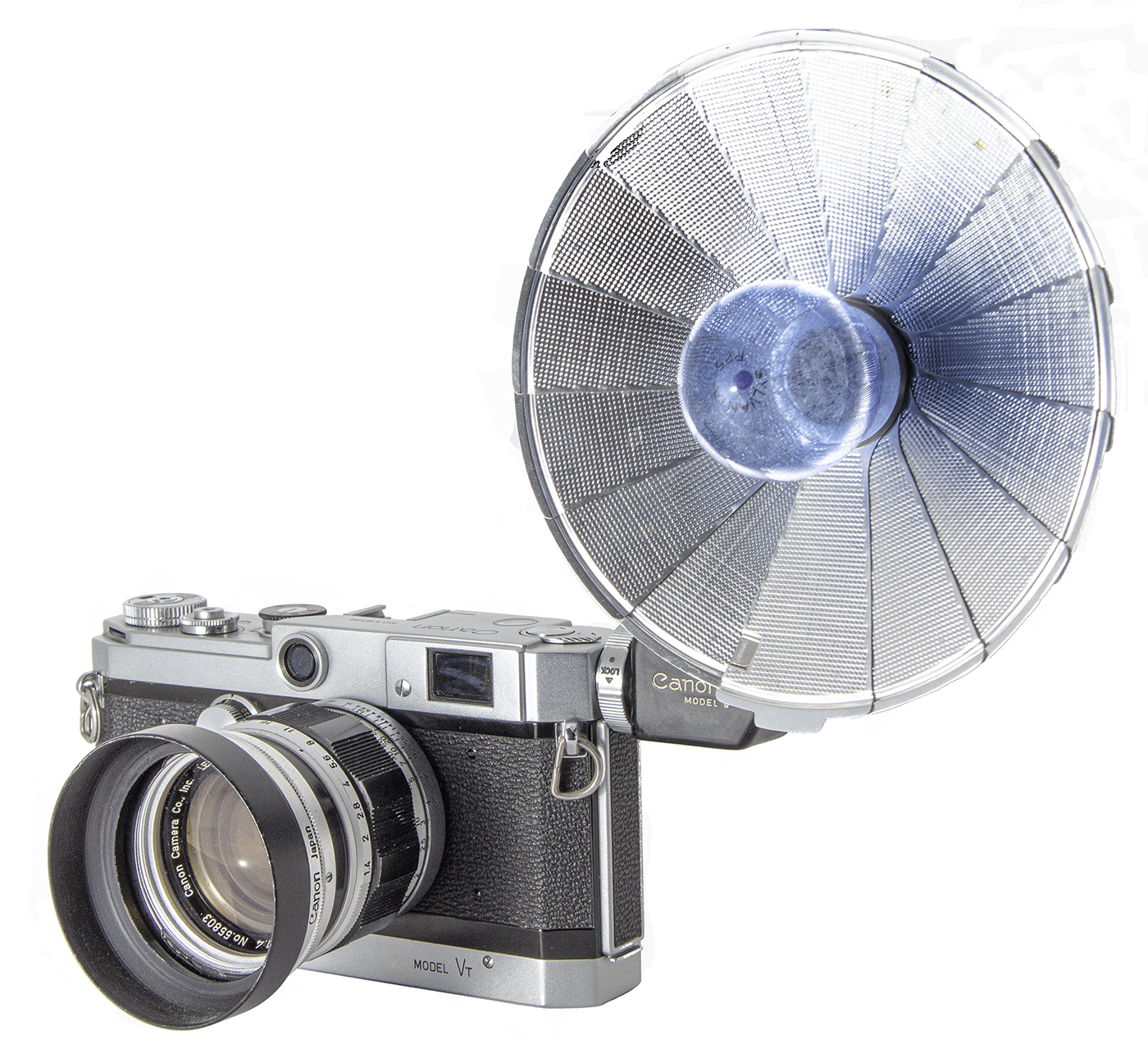
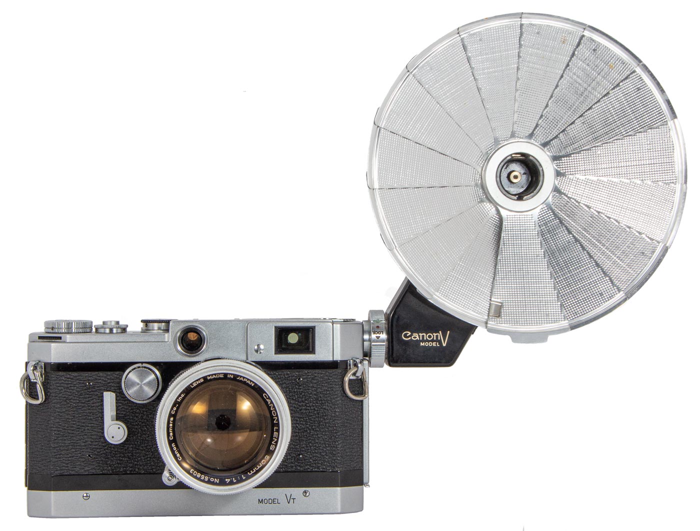
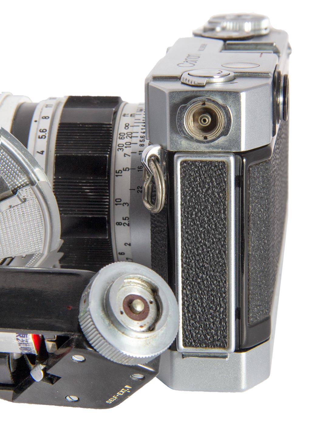
The Model VT was the first to mount the “Flash Unit Connector Socket” as is shown here. The flash attaches solidly and is out of the way of the operators hands and his access to the cameras controls.
The Flash Unit Connector Socket was mounted on the left end of the camera at the top where it would remain through the rest of the rangefinder cameras and through to the end of the Canonflex series.
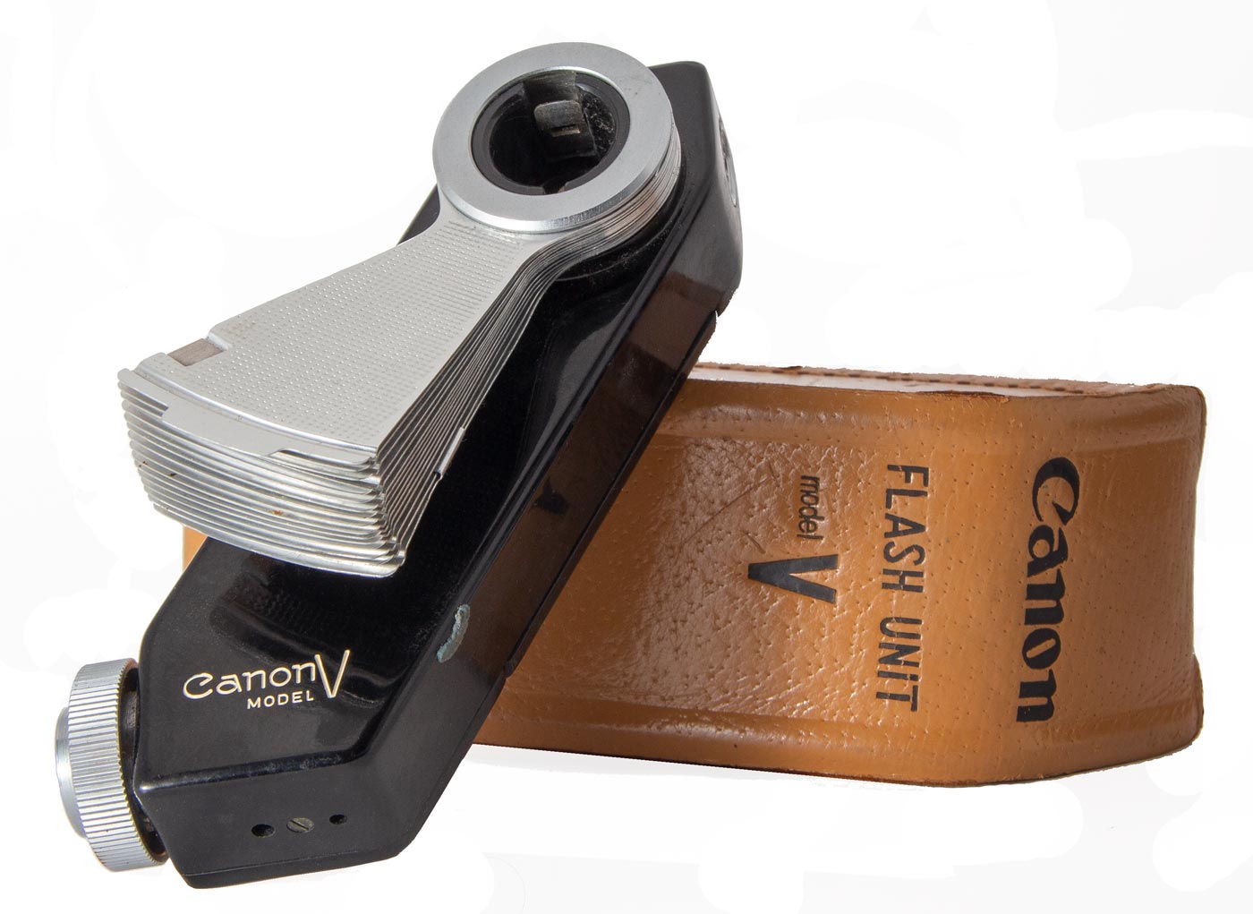
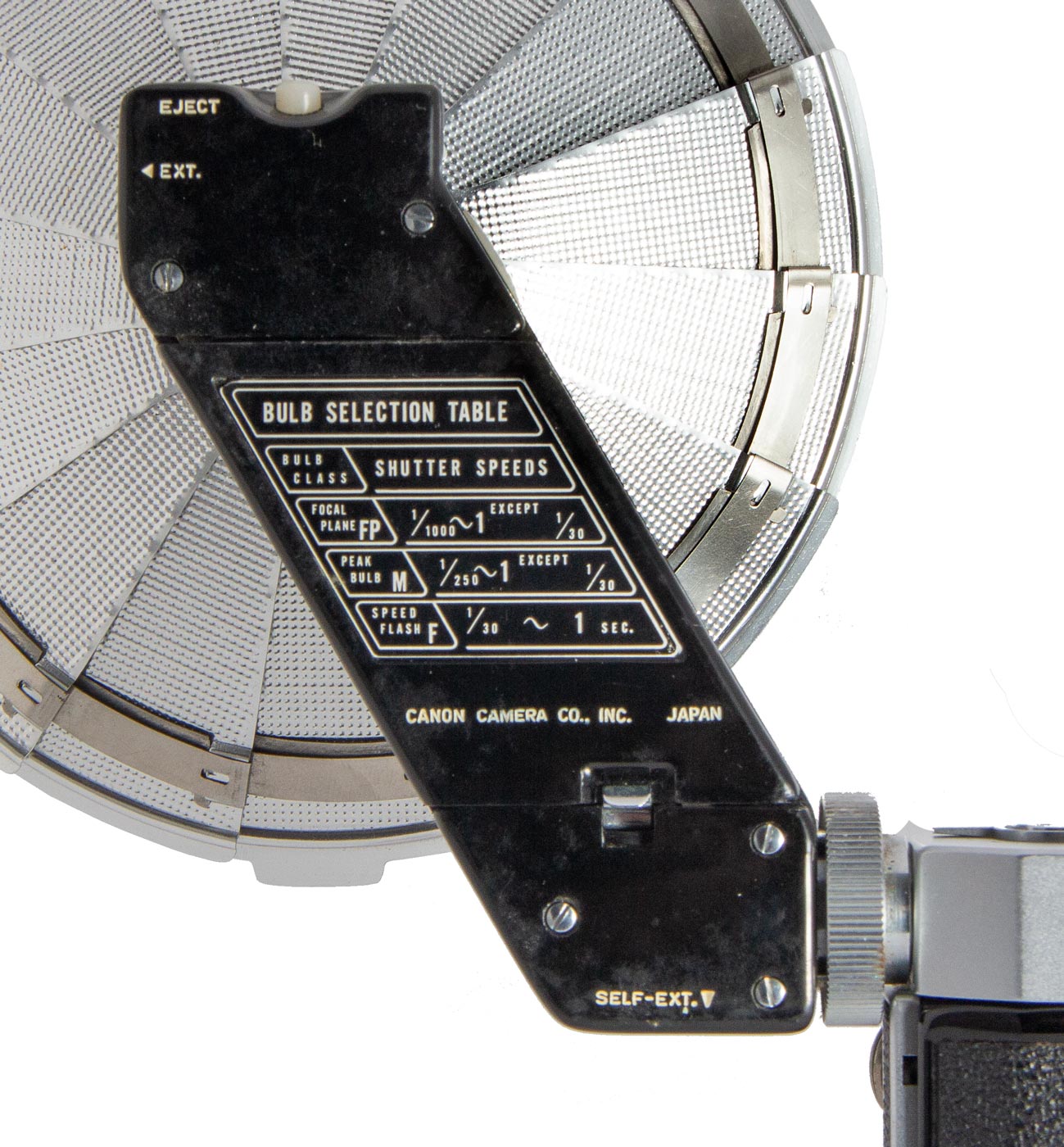
The metal reflector is segmented and it collapses for stowing in the leather case. Bayonet base bulbs snap in and release with the press of a button on the top.
The metal reflector is segmented and it collapses for stowing in the leather case. Bayonet base bulbs snap in and release with the press of a button on the top.
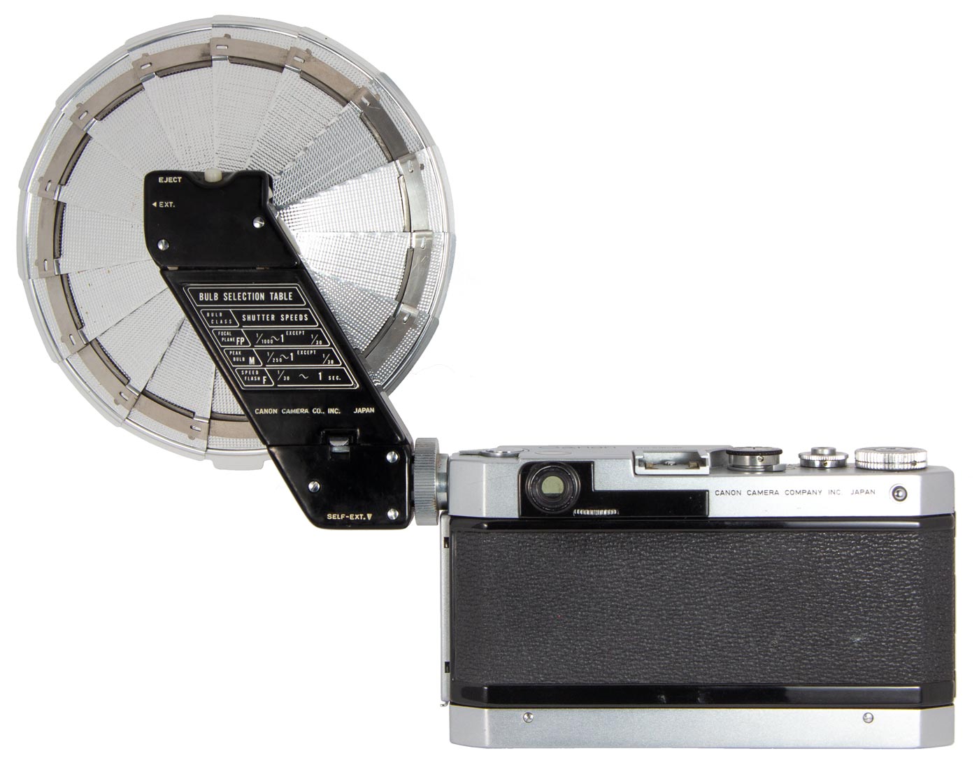
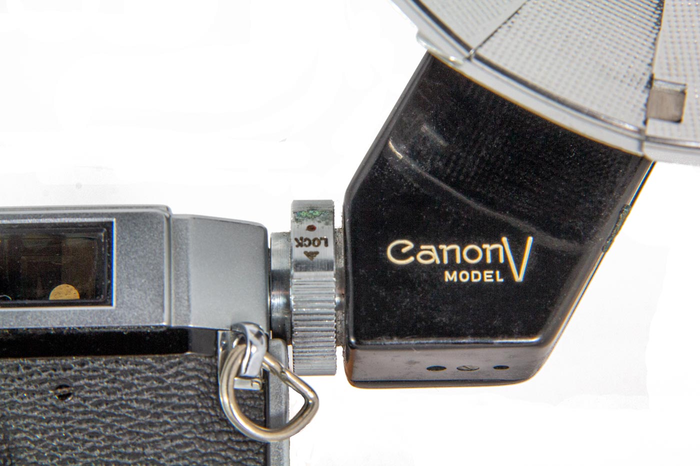
From the back the clean lines of the mounting are obvious. And the mount is strong. The Flash Unit does not move in the mounting once the mounting collar is tightened.
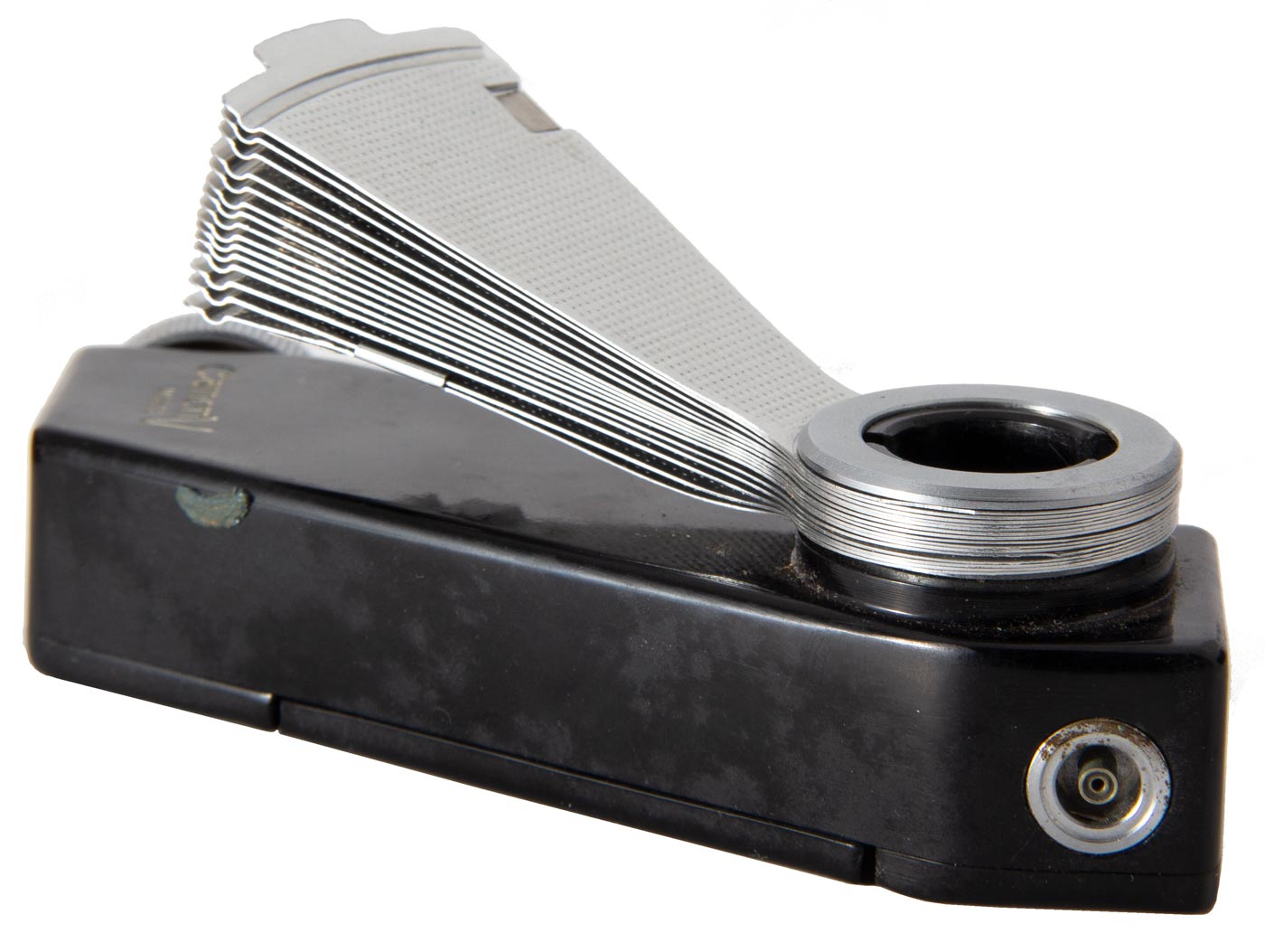
The Model V has a PC Socket which allows the Unit to sync another off camera flash. This allowed more sophisticated lighting setups.
The Flash Unit Connector Socket mount is very sturdy. The Flash Unit pushes into the Socket and then a collar is rotated to lock it in securely in place.
Both halves of the connection are visible here. The locking lugs on the camera half mesh with the rotating ring on the Falsh Unit.
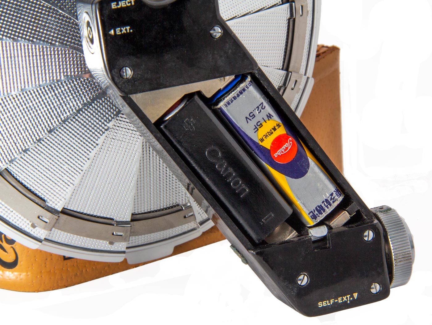
The back of the Flash Unit comes off to reveal the 22.5 volt battery and capacitor. The capacitor stored a charge from the battery which, with the battery, delivered a larger surge of current to ensure good ignition of the flash buld.
Inside of the body of the Flash Unit is a 22.5 volt battery and a large capacity capacitor. When the electical contacts in the camera close the battery and capacitor are applied across the flash bulb contacts which sends a surge of current through the circuit and a wire inside the flash bulb. This ignites the fine wire which in turn ignites the metalic shavings in the low pressure oxygen atmosphere. The metal immediatly flashes into brilliance and then dies.
By having a large capacity capacitor in the circuit the surge of current to ignite the bulb is stronger resulting in more reliable ignition.
The Flash Unit V will work with any camera with the Flash Unit Connector Socket. This gives the Flash Unit Model V a range of cameras with which it can be paired.
User Manual for the Canon Fl;ash Unit V
This website is the work of R. Flynn Marr who is solely responsible for its contents which are subject to his claim of copyright. User Manuals, Brochures and Advertising Materials of Canon and other manufacturers available on this site are subject to the copyright claims and are the property of Canon and other manufacturers and they are offered here for personal use only.

