The Flash Coupler
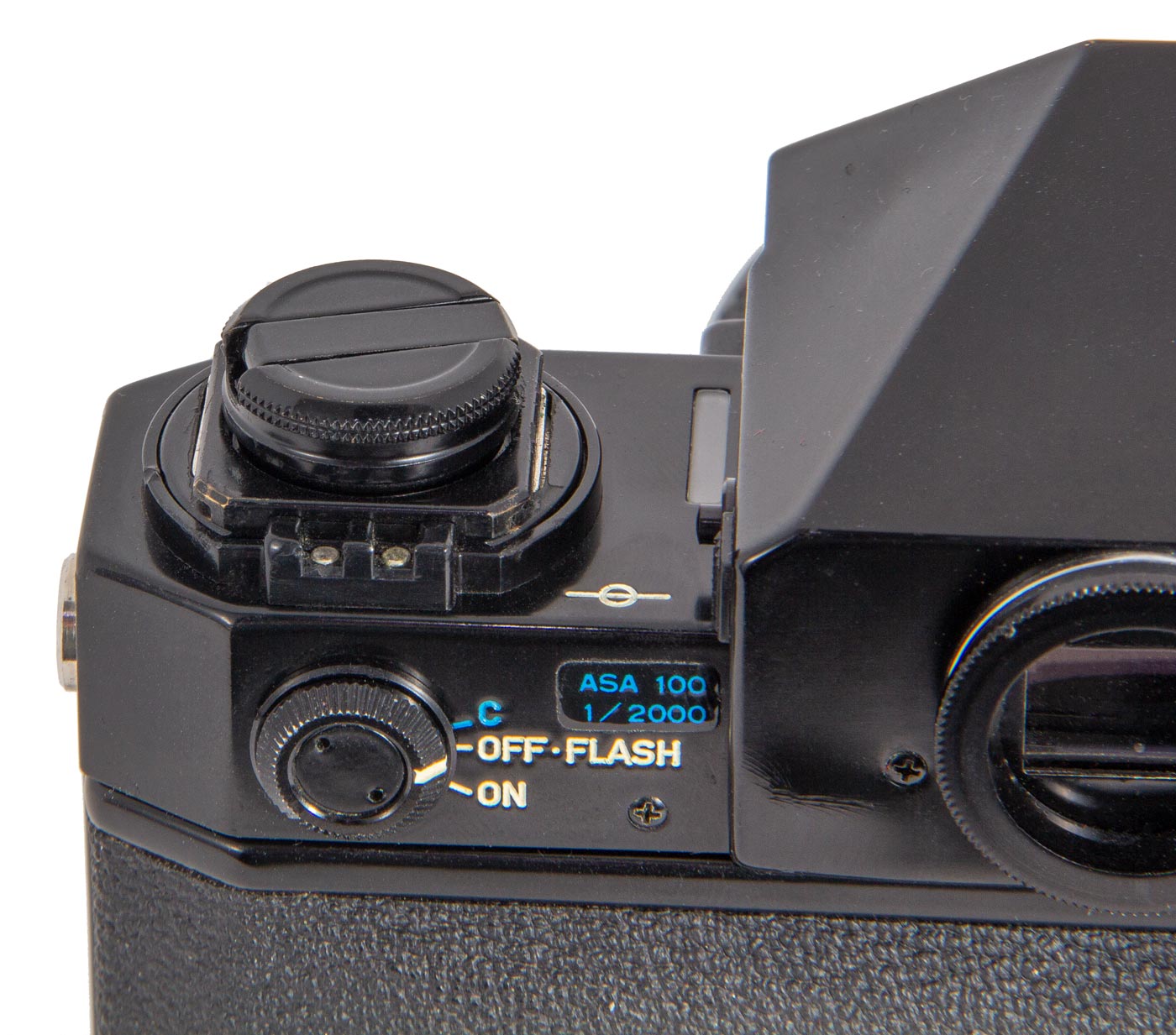
The Canon F-1 and the F-1n have no hot shoe or equipment shoe to mount a Flash Unit or Speedlite. However, on the left end of the top deck there is a PC Shoe for flash sync. There are also sync connections in the collar that surrounds the rewind crank.
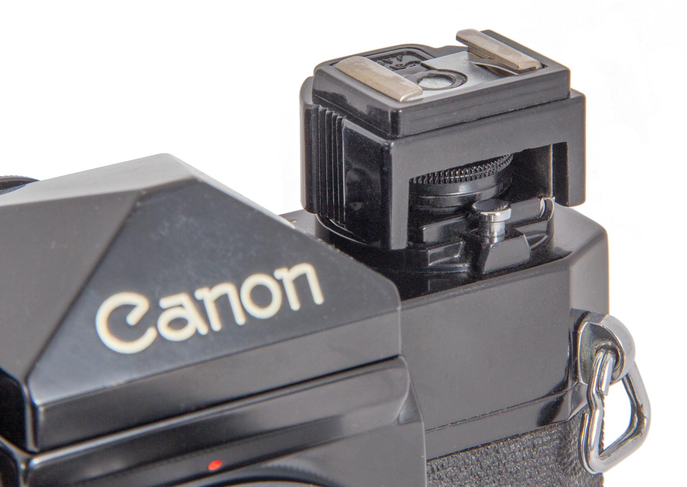
That collar around the rewind crank also contains rails into which the user can insert a “Flash Coupler”, a device that adds a hot shoe to the left side of the camera.
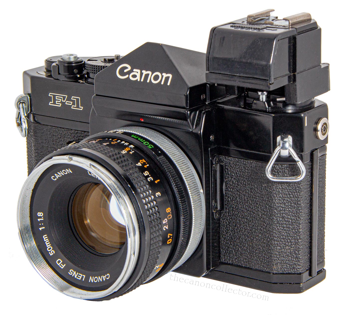
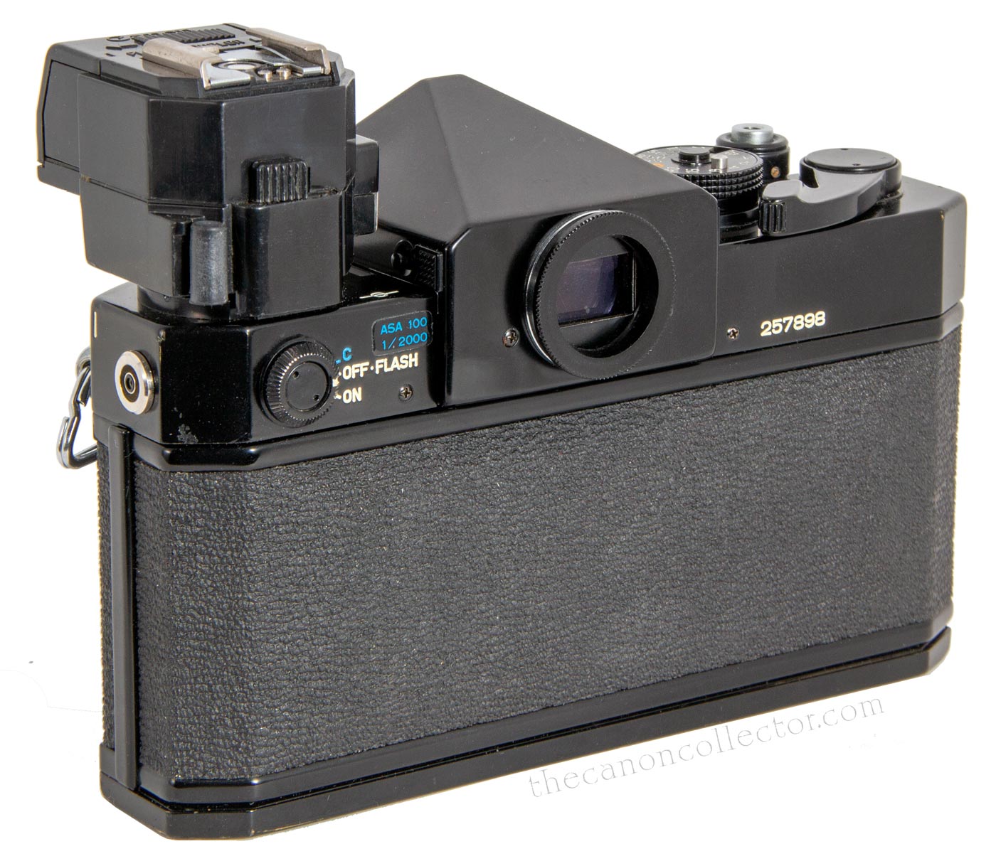
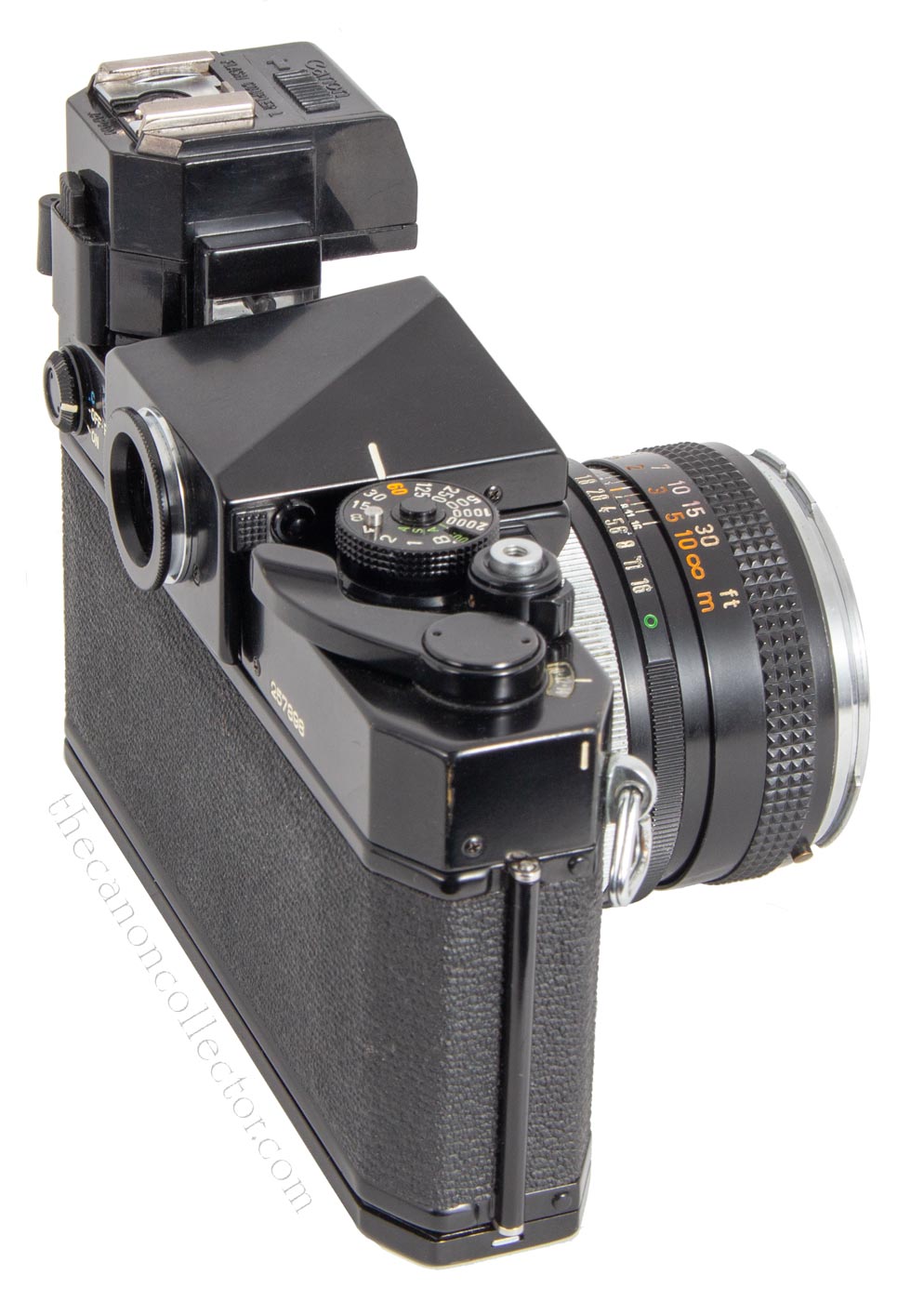
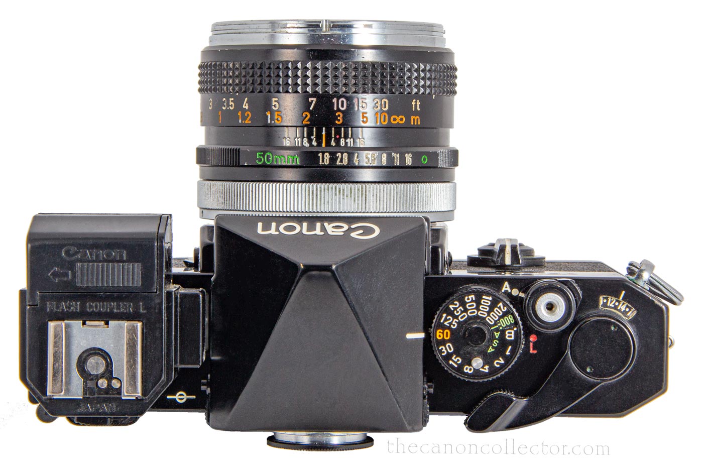
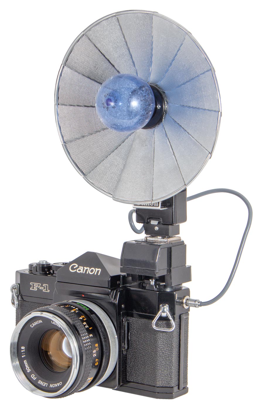
There are three Flash Couplers: there is the Flash Coupler D, Flash Coupler L and the Flash Coupler F. The D is the simplest simply adding a hot shoe. The L is the same but it adds a lock to hold it in the camera and a light to illuminate the meter needle in the viewfinder for camera use in dark locations. And finally, the F simply adds a hot show but it sits not on the left side of the camera but over the pentaprism.
Simple devices that extend the capabilities of the F-1 system, we will look at them one at a time.
The F-1 has no hot shoe, or equipment shoe of any kind. However there is a PC Socket on the left end of the body and two electrical contacts for flash sync located behind the collar around the rewind crank.
Flash Coupler D
The Flash Coupler D slides on, from the back, over the Rewind Crank. It sits over the rewind crank while in use however, it must be removed for film loading or unloading.
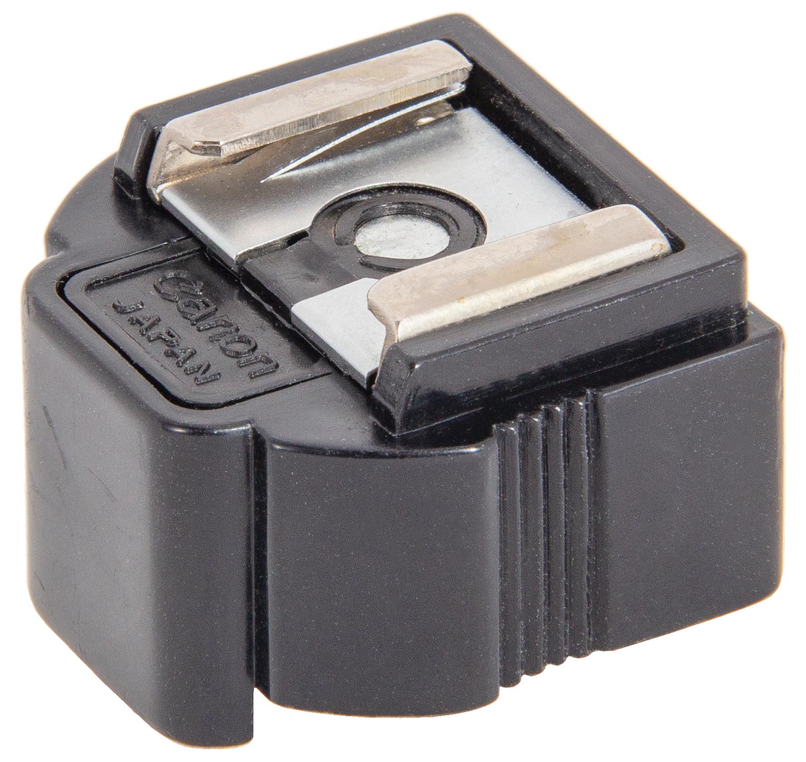
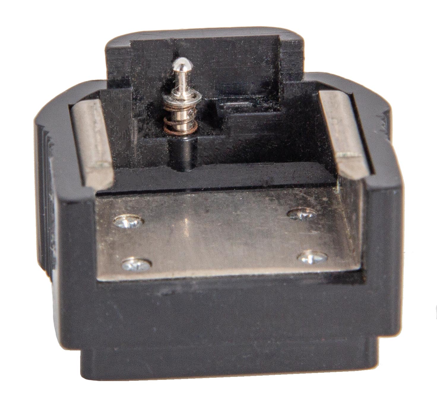
The Flash Coupler D is the simplest of the Couplers. It slides over the rewind crank and sits on top of it. It makes contact with one of the sync contacts behind the rewind crank and provides a simple hot shoe.
The Flash Coupler D has no lock so it relys on a friction fit to stay securely on the camera. This is a good tight fit on my camera but I don’t know what happens with considerable wear and tear.
Because this Flash Coupler sits over the rewind crank the camera cannot be opened and film cannot be rewound with it in place. It must be removed to load or unload film.
Flash Coupler L
The Flash Coupler L slips on over the rewind crank on the F-1 just like the Coupler D does. But the size difference is immediately obvious.
In early strobe units there was a problem with the charge on the flash capacitor that stored the electrical energy to power the flash tube. The capacitor takes time to charge and the level of charge can change with time. Light output is determined by the charge on the capacitor which affects the exposure of the film.
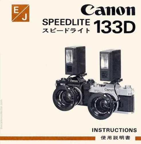
Canon created a system to adjust for this variation in charge which they called their CAT (Canon Auto Tuning) System. The 133D strobe unit was designed to report the capacitor charge to the camera exposure metering system so it could adjust the meter reading to compensate for it. The Flash Coupler L was designed to take advantage of this sytem when using the 133D Speedlite.
The Coupler L slides over the rewind crank in the same way as the Coupler D. It is larger physically because Canon has added two features to this unit which has required the addition of two batteries to power them.
The first new feature is a light bulb to illuminate the meter needle visible in the view finder. Normally the
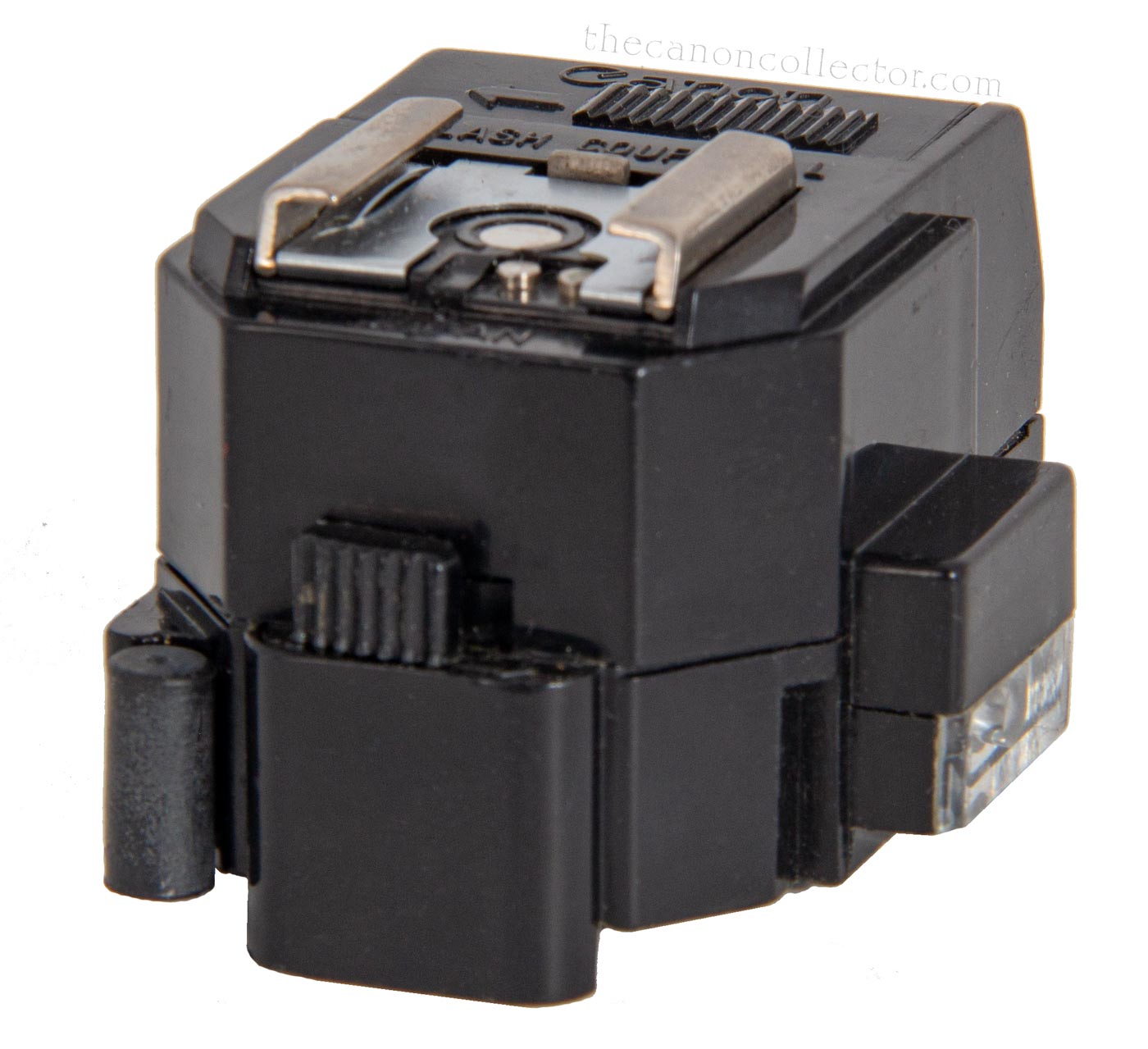
The Flash Coupler L slips over the rewind crank from the rear. On the back is the switch to turn the meter needle illumination on and the lock handle for locking the unit on the camera.
The Coupler L extends further forward than the Coupler D and that is where the two batteries that power it are stored.
needle is illuminated by ambient light entering through a window on the top deck lying beside the left side of the pentaprism. An extension on the right side of the Flash Coupler L which contains a small light bulb. This projection sits out over the window and the light bulb shines down into it. The result is that the meter is illuminated regardless of light conditions around the camera. There is a slide switch on the back of the coupler to turn the bulb on and off.
The second battery powers the CAT system. The functioning of this method of exposure compensation we will cover when we have a look at the Speedlite 133D. It is complex and not often encountered. Because of the improvements in flash systems it is unlikely you will ever need to consider using this system.
In the middle of the back of the Flash Coupler L is the switch that controls the illumination bulb which can be seen on the right edge in this picture.
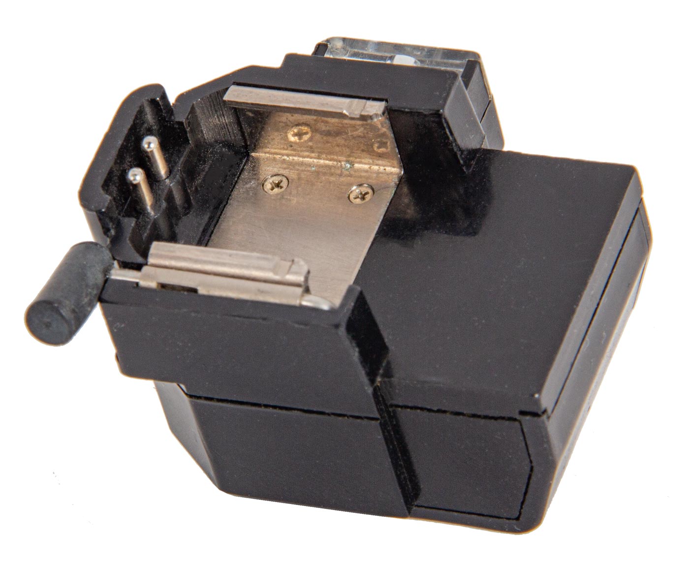
The bottom of the Flash Coupler L reveals the two electrical contacts necessary for the operation of the flash and of the CAT System. They are visible as two pins on the left edge.
The Flash Coupler L comes boxed with an Instruction Sheet. It doesnèt reeally say very much.
Flash Coupler F
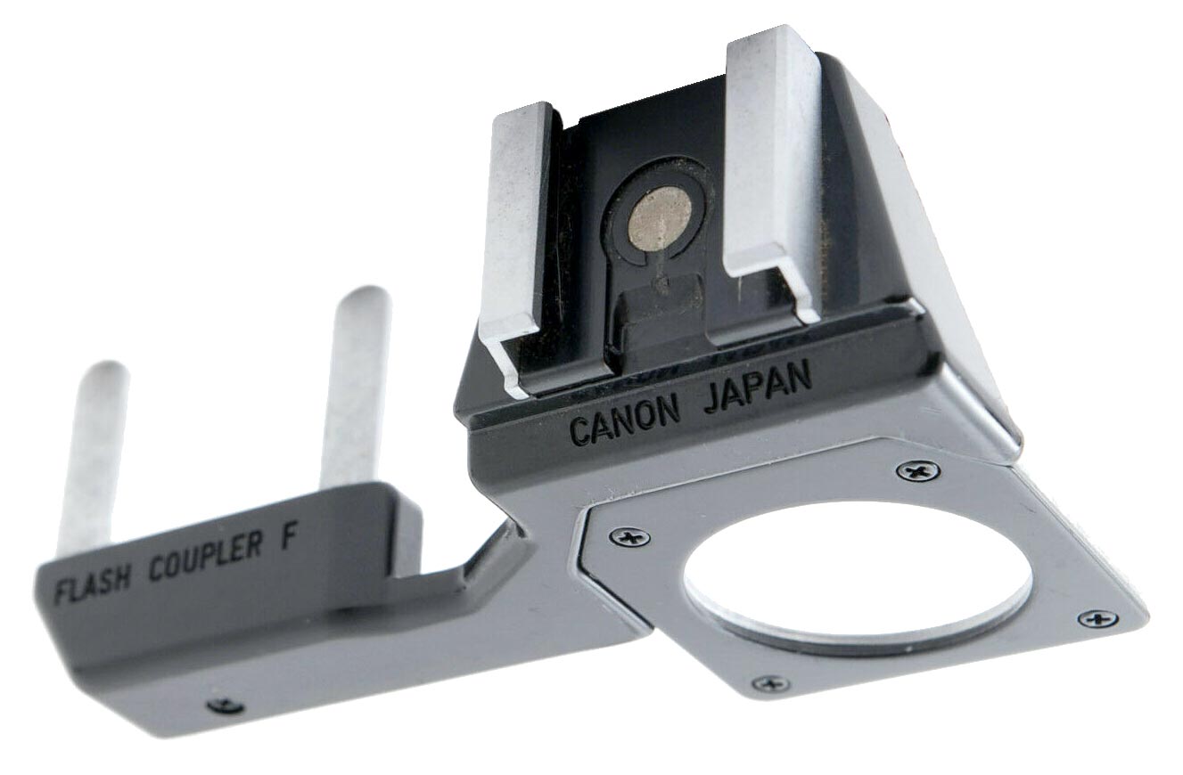
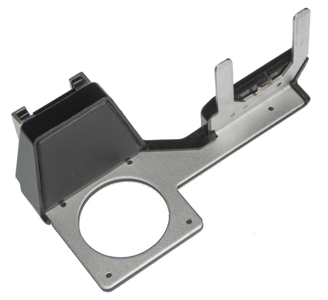
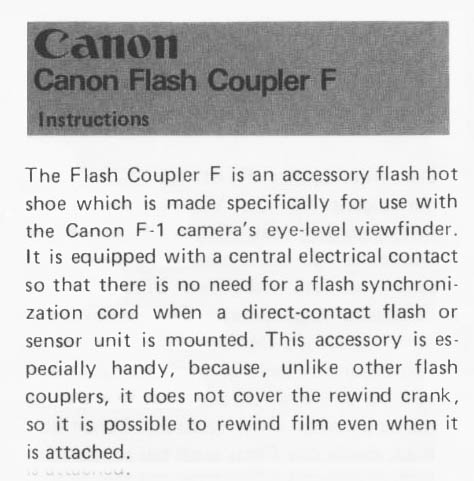
Unfortunately I do not yet have a copy of the Flash Coupler F. It is a neat device than gives the F-1 a hot shoe above the eyepiece over the pentaprism. You get the hotshoe and you can still use the rewind crank.
The Coupler F is attached by takng the eyepiece off and fitting the unit over it. The two prongs fit in the groves under the rewind crank. The eyepiece that comes with the unit is then screwed in around the eyepiece thus securing the Coupler F.
The Instruction sheet that comes with the Flash Cupler F is not very helpfull but it does give instructions for how to install it.
This website is the work of R. Flynn Marr who is solely responsible for its contents which are subject to his claim of copyright. User Manuals, Brochures and Advertising Materials of Canon and other manufacturers available on this site are subject to the copyright claims and are the property of Canon and other manufacturers and they are offered here for personal use only.


